
Concept explainers
Videos
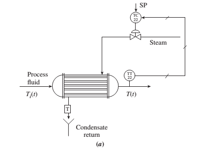
Figure P9.6(a) shows a heat-exchanger process whose purpose is to maintain the temperature of a liquid at a prescribed temperature.
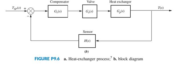
The temperature is measured using a sensor and a transmitter, TT 22, that sends the measurement to a corresponding controller, TC 22, that compares the actual temperature with a desired temperature set point, SP. The controller automatically opens or closes a valve to allow or prevent the flow of steam to change the temperature in the tank. The corresponding block diagram for this system is shown in Figure P9.6(b) (Smith, 2002).
Assume the following transfer functions:
a. Assuming
b. Design a PD controller to obtain the same damping factor as Part a but with a settling time 20% smaller.
c. Verify your results through MATLAB simulation.
MATLAB
ML
Want to see the full answer?
Check out a sample textbook solution
Chapter 9 Solutions
Control Systems Engineering


- After some engine model replacement, an aircraft model is experiencing some aggressive nose up phenomenon which may lead to stall. To combat this problem, a new control system has been introduced to the Flight Control Computer, FCC. When activated, the new system measure the aircraft pitch from an Angle of Attack, AOA sensor to analyze either the aircraft is nosing up or down. If the pitch angle is too high, describing that the aircraft might be in a dangerously nose up position, the FCC will gain control of the horizontal stabilizer using a linear motor (FIG 1), thus bringing the nose of the aircraft down into safer pitch angle range (FIG 2). a. What is the input/output of the control system? b. Is this system is a close loop or open loop? c. What is the actuator used in this control system? d. Draw the Block Diagram to describe the control system. Horizontal stabilizer Pivot Horizontal stabilizer 000000c Jackscrew moves the angle of the horizontal stabilizer up or down. Motor Figure…arrow_forwardQ: Discuss the control system (the level controller and the temperature controllers) shown in figure (2). Specify the controlled and manipulated variable in each case. Discuss the type of the controller used in each case, that is, a simple feedback controller, a feedforward controller, a cascade controller, etc. Draw the block diagram of the temperature control loops. Feed Reactor temperature set point (master) TC Water surge tank i Jacket itemperature i set point (slave) TC LC-LT Reactor Cooling water out Product Cooling water makeup Circulation pump Figure (2)arrow_forwardO 17161489 C Get Homework Help With b My Questions | bartleby O Mail - Castro Alvarez, Flavic X Content A learn-us-east-1-prod-fleet01-xythos.s3.amazonaws.com/5c1270dbb5a74/17161489?response-cache-control=private%2C%20max-age%3D21600&respon. ☆ ME 3022 - HW 19 1. (More practice from Monday) A 90° elbow in a horizontal pipe is used to direct a flow of oil (SG = 0.87) upward at a rate of 40 kg/s. The cross- sectional diameter of the elbow is a constant 20 cm. The elbow discharges at A into a large holding tank where the level of oil is 1.8 m above A. The 50 cm "weight" of the elbow and the oil in it is 50 kg. Determine (a) the gage pressure at the inlet of the elbow and (b) the anchoring force needed to hold the elbow stationary. Take the momentum-flux correction factor to be 1.03 40 kg/s at both the inlet and the outlet. Activar Windows Ve a Configuración para activar Windows. Esperando blackboard.ohio.edu. 17:07 P Escribe aquí para buscar a ) ENG 14/10/2020 近arrow_forward
- In order to stabilize the system, we use a P controller in cascade with the feed-forward chain as shown in the following block diagram: U(s) 1 Y(s) K s3+5s²+ 4s Determine the range of K in the P controller that makes the system stable. (K is always positive) Select one: O a. K> 1 O b. The system is never stable О с. К 15 е. К < 20arrow_forwardotINote: The notation from this problem is from Understanding Cryptography by Paar and Pelzl. We conduct a known-plaintext attack against an LFSR. Through trial and error we have determined that the number of states is m = 4. The plaintext given by when encrypted by the LFSR produced the ciphertext 01011000 = yo yı y2 ys Yo Y %3D What are the tap bits of the LFSR? Please enter your answer as unspaced binary digits (e.g. 0101 to represent py = 0, P = 1, P = 0, Po= 1).arrow_forwardThe temperature of a catalysed exothermic reaction is being maintained at T1°C as it promotes generation of a particular product. It is proposed to control the temperature with a proportional only controller of gain Kc. The temperature dynamics of the reactor can be modelled as a mixture of a CSTR (1st order) and PFR (dead time) to changes either in inlet temperature, or in the heating/cooling jacket flowrate via Ke-tas Ts+1 i) Considering a change in inlet temperature show why a 1st order model for a CSTR and a dead time model for a PFR are appropriate. CSTR - continuous stirred tank reactor PFR - plug flow reactorarrow_forward
- The temperature of a catalysed exothermic reaction is being maintained at T1°C as it promotes generation of a particular product. It is proposed to control the temperature with a proportional only controller of gain Kc. The temperature dynamics of the reactor can be modelled as a mixture of a CSTR (1* order) and PFR (dead time) to changes either in inlet temperature, or in the heating/cooling jacket flowrate via Ke-'a® Ts+1 i) Considering a change in inlet temperature show why a 1st order model for a CSTR and a dead time model for a PFR are appropriate. CSTR - continuous stirred tank reactor PFR - plug flow reactorarrow_forwardPleasearrow_forwardGiven the following discrete time system where y[n] is the system output and x[n] is the input, indicate which of the provided options are the discrete poles of the system. yln] = 0.7y[n – 1] – 0.4y[n – 2] + 2x[n – 1] + 4x[n – 3] Select one: O a. 0.5 + j0.9634 O b. 0.35 + j0.52 O c. -0.25 + j0.45 O d. 0.35 + j0.152arrow_forward
- Using the following lines, let us create a virtual data concerning the joint torque (Nm) and angular velocity (RPM) of an imaginary actuator system: Kx = 29; Kn 200; dt 0.001; %sampling time 10; simulation time Ts ns Ts/dt +1; for i = 1:nS t(i) tau (i) = (i-1) *dt; time variable Kx*sin (2*pi*0.5*t (i)) + = 0.1*sin (2*pi*50*t (i)); dq (i) = Kn*cos (2*pi*0.5*t (i))*9.24; SOME CALCULATONS HERE end & THEN SOME OTHE CALCULATIONS HERE Calculate the average torque T_avg. Then referring the Harmonic Drive Catalogue, choose a gear model with a gear ratio of 1:30 in accordance with the T_avg value you calculated. Explain the rationale behind your choice.arrow_forward2- Using Matlab, what are the step response curves of the closed-loop system, as shown in fig.1. the feedback represents the second-order dynamic system. (fill in the following table) For=0.4 Wn 1 3 6 9 10 R(S) 0.1 0.3 0.6 0.9 1 For w 5 rad/sec 3 Settling time Peak response 2 Wn s(s+23wn) Settling time Peak response C(s) Discuss the follow Which parameters or w occur on the rise time of the response? Which parameter increases the speed of response? Which parameters can be decreases the response amplitude? Which parameter decreases the steady error state? fig.2arrow_forwardQUESTION 10 A cruise control system is implemented on an expensive ferrari and results in closed-loop dynamics modelled by the equation 3 dv/dt + 0.9 v = 0.8 r where r is the target velocity and v is the actual velocity and the time scale is seconds. Which of the following statements are true? Do not guess as incorrect answers are penalised. Only select the statements you are sure are correct. The system velocity diverges. The system has satisfactory dynamics. The system converges to a zero steady-state error. None of these. The system does not reach the required velocity. The system has slow dynamics."arrow_forward
 Elements Of ElectromagneticsMechanical EngineeringISBN:9780190698614Author:Sadiku, Matthew N. O.Publisher:Oxford University Press
 Mechanics of Materials (10th Edition)Mechanical EngineeringISBN:9780134319650Author:Russell C. HibbelerPublisher:PEARSON
 Thermodynamics: An Engineering ApproachMechanical EngineeringISBN:9781259822674Author:Yunus A. Cengel Dr., Michael A. BolesPublisher:McGraw-Hill Education
 Control Systems EngineeringMechanical EngineeringISBN:9781118170519Author:Norman S. NisePublisher:WILEY
 Mechanics of Materials (MindTap Course List)Mechanical EngineeringISBN:9781337093347Author:Barry J. Goodno, James M. GerePublisher:Cengage Learning
 Engineering Mechanics: StaticsMechanical EngineeringISBN:9781118807330Author:James L. Meriam, L. G. Kraige, J. N. BoltonPublisher:WILEY