
Control Systems Engineering
7th Edition
ISBN: 9781118170519
Author: Norman S. Nise
Publisher: WILEY
expand_more
expand_more
format_list_bulleted
Concept explainers
Videos
Textbook Question
Chapter 9, Problem 25P
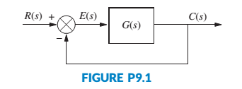
For the unity feedback system in Figure P9.1, with
design a PID controller that will yield a peak time of 1.122 seconds and a damping ratio of 0.707, with zero error for a step input. [Section: 9.4]
Expert Solution & Answer
Want to see the full answer?
Check out a sample textbook solution
Students have asked these similar questions
For a unity negative feedback control system having an open-loop transfer function, G(s) as given
below. Find out the value of "K" such that the system will be in the stable region.
(K/s)
(s3 + 12. 5s2 + 50. 5s + 66)
G(s) =
and
1)
2)
LIUS
S
Consider the following feedback system, where K is a constant gain
G(s) ===
1
s3 +382 +s+1
Let K be a real number. Utilize the Routh-Hurwitz criterion to derive
stability conditions for the closed-loop system.
Suppose that the reference input r(t) = 1. What are the steady-state
tracking errors (ess) for K = 1 and K = 3, respectively?
R
K
G(s)
Y
Figure 2: Control system in Problem 2.
P6. The open loop transfer function of a unity feedback
system is
K(s+2)
G (s) =
s(s+3)(s²+2s+10)
1- Find the value of K so that the error steady state
for the unit ramp input r(t)=t is less than or equal
to 0.01.
2-For the value of K found in part (1), use the Routh
method to verify whether the closed loop system is
stable.
Chapter 9 Solutions
Control Systems Engineering
Ch. 9 - Prob. 1RQCh. 9 - Name two major advantages of the design techniques...Ch. 9 - What kind of compensation improves the...Ch. 9 - 4. What kind of compensation improves transient...Ch. 9 - 5. What kind of compensation improves both...Ch. 9 - Prob. 6RQCh. 9 - Prob. 7RQCh. 9 - What difference on the s-plane is noted between...Ch. 9 - Prob. 9RQCh. 9 - Why is there more improvement in steady-state...
Ch. 9 - Prob. 11RQCh. 9 - 12. A lag compensator with the zero 25 times as...Ch. 9 - Prob. 13RQCh. 9 - Prob. 14RQCh. 9 - The unity feedback system shown in Figure P9.1...Ch. 9 - Prob. 18PCh. 9 - Prob. 19PCh. 9 - Prob. 22PCh. 9 - For the unity feedback system in Figure P9.1, with...Ch. 9 - Prob. 26PCh. 9 - Prob. 29PCh. 9 - Prob. 31PCh. 9 - Prob. 32PCh. 9 - Prob. 34PCh. 9 - Identify and realize the following compensators...Ch. 9 - Prob. 36PCh. 9 - Prob. 37PCh. 9 - Figure P9.5 shows a two-tank system. The liquid...Ch. 9 - Figure P9.6(a) shows a heat-exchanger process...Ch. 9 - Repeat Problem 39, Parts b and c, using a lead...Ch. 9 - Prob. 41PCh. 9 - 42. You are given the motor whose transfer...Ch. 9 - Prob. 43PCh. 9 - A position control is to be designed with a 10%...Ch. 9 - Prob. 45PCh. 9 - Prob. 46PCh. 9 - Prob. 47PCh. 9 - Repeat Problem 47 using a lag-lead compensator...Ch. 9 - Prob. 51PCh. 9 - A metering pump is a pump capable of delivering a...
Knowledge Booster


Learn more about
Need a deep-dive on the concept behind this application? Look no further. Learn more about this topic, mechanical-engineering and related others by exploring similar questions and additional content below.Similar questions
- b) Closed-loop transfer function of a unity-feedback system is given by Y(s) / R(s)=1/(ts+1) .Discuss steady-state error for positional, velocity, and acceleration input?arrow_forwardA second order plant with unity feedback is cascaded by a proportional controller as shown. If K is 100, 1. HI. Determine its closed-loop poles Y(s)/R(s). Determine its transfer function of E(s)/R(s) Calculate the steady state error of the following block diagram for a unit step R(s) input. iv. Suggest a method to improve on the steady state error. E(s) K pito 7 (s+2)(s+5) Y(s)arrow_forward1. Give an example of open loop and closed loop system (one example each). Also state the input, control system, feedback and output parameter. Example. 1. Open Loop - Water Heater: Input - Water Temperature (Cold) System - Heating Element Output - Water Temperature (Hot) 2. Closed Loop - Air-conditioning System Input - Desired Room Temperature Control - Motor controller/Compressor/ACU Feedback - Temperature Sensing Output - Room Temperaturearrow_forward
- Consider the plant with transfer function G(s) connected in standard feedback configuration with the controller De(s) = K. 1) 2) = s+2 (s+1)²+1 Sketch the root locus for G(s). Explain what rules you used to plot it. (Be sure to describe the following: the number of branches, where they start and where they are going; the real-axis portion of the root locus; jw-axis crossings (if any); points of multiple roots (if any).) What conditions need to be imposed if we want our closed-loop system to have no oscillations under a step input? Explain the conditions from the root locus. + Ro Σ Dc(s) G(s) Figure 1: Control system in Problem 1.arrow_forwardblock diagram pls solve fast As Simplify the multiple loop feedback control system? R(s) G₁ G₂ H3 H₂ + G3 H₁ G₁ Y(s)arrow_forwardThe satallite system below is controlled using reaction wheels. The torque wheel input for the system is u(s) and the satallite attitude is Ө(s) For a strong communication link Ө needs to be a value where the satallite atenna is pointing at the ground station The transfer function for this system will be shown in the picture. Design a feedback control system that sets the closed loop damping ratio at 0.8 and the natural frequency is at 10 rad/sec.arrow_forward
- Evaluation of a system's error i. A unity feedback system has the following forward transfer function: 6.63K G(s) = s(s+1.71)(s+100)arrow_forward1) Consider the system below: Vehicle Controller Steering dynamics Desired Actual bearing angle bearing angle 50 1 K s2 + 10s + 50 s(s + 5) Figure 1: Simplified Block Diagram of a Self-Guiding Vehicle's Bearing Angle Control. • Find a K value that the system has minimum rise time and minimum overshoot. Let us call this proportional gain as Kopt Show each step while finding Kopt- Show the necessary graphical solutions. Simulate the system response with 3 different K values. (Kopt and two other K values close to Kopt) Show the system response (actual bearing angle) in a single graph for different K values. • Comment on the results.arrow_forwardHomework: For a unity feedback system with the forward transfer function: K(s + 20) G(s) = s(s + 2)(s+3) find the range of K to make the system stable.arrow_forward
- For the unity negative feedback systems, G(s) = resonant frequency W₁ ≤ 6 and estep (0) = 0. (s+2)(s+12)' design a Pl controller such that thearrow_forwardWe consider a dynamical system represented by the block diagram: Simple negative feedback: U(s) E(s) input, + with T₁(s) = T₂(s) = 3 + T,(s) 1 S T₂(s) a s²(1+s) X(S) output measurement with a 4 and Calculate the open-loop transfer function at s=6.arrow_forwardP.5: For the unity feedback system shown K(s + a) (s+B)² G(s) is to be designed to meet the following specifications: steady-state unit step input = 0.1; damping ratio = 0.5; natural frequency K, a, and B. = error for a √10. Find R(s) + E(s) G(s) C(s)arrow_forward
arrow_back_ios
SEE MORE QUESTIONS
arrow_forward_ios
Recommended textbooks for you
 Understanding Motor ControlsMechanical EngineeringISBN:9781337798686Author:Stephen L. HermanPublisher:Delmar Cengage Learning
Understanding Motor Controls
Mechanical Engineering
ISBN:9781337798686
Author:Stephen L. Herman
Publisher:Delmar Cengage Learning
The Robot Revolution: The New Age of Manufacturing | Moving Upstream; Author: Wall Street Journal;https://www.youtube.com/watch?v=HX6M4QunVmA;License: Standard Youtube License