
Concept explainers
Videos
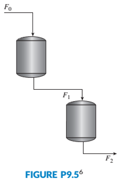
Figure P9.5 shows a two-tank system. The liquid inflow to the upper tank can be controlled using a valve and is represented by
a. Assuming
b. Verify your design through MATLAB simulations.
MATIAB
ML
Want to see the full answer?
Check out a sample textbook solution
Chapter 9 Solutions
Control Systems Engineering


- Name two effects of negative feedback.arrow_forwardIdentify the following elements of the given closed loop control system.(i) Process Element(ii) Feedback Element (iii) Control Element (iv) Correction Elementarrow_forwardIn an industry, the water in a boiler tank needs to be kept at constant pressure, water to the tank comes at constant flow rate and steam is coming from a valve to maintain the pressure. A pressure gauge is used to measure the water pressure in the tank. a. Provide the block diagram representation using a PID controller for the above mentioned condition (Control the pressure using the proportional valve.). b. explain the working principle.arrow_forward
- Determine the controllability and observability for this systemarrow_forwardExamine the following while loops and determine the value of ires at the end of each of the loops, and the number of times each loop executes. (a) ires - 1; while mod (ires, 21) = 0 iresires + 1; end ires = number of times ires= 2; while ires 100 iresires^2; end number of times (b) (c)arrow_forward(PID solution with the requirements and simple explanation. Thx) INSTRUCTION: Given three bare processes develop a control system using feedbackand feedforward concept/principle. Your output is a process and instrumentationdiagram (P & ID) using ISA's Instrument Identification and Symbols standards withexplanation. PROCESS 2: The liquid level inside the tank is regulated at a value of 3.0 m on a condition ofcontinuous liquid inflow and outflow. Requirements: Two feedback solutions One feedforward solutionarrow_forward
- b) Consider the evaporator which concentrated the salt solution and the transfer functions of all open systems are first-order system. 1) Design the cascade control loop and block diagram. If the evaporator temperature and steam flowrate of coil are controllerd variables and if the inlet concentration and presure of coil steam are disurbance variables.arrow_forwardQUESTION 10 A cruise control system is implemented on an expensive ferrari and results in closed-loop dynamics modelled by the equation 3 dv/dt + 0.9 v = 0.8 r where r is the target velocity and v is the actual velocity and the time scale is seconds. Which of the following statements are true? Do not guess as incorrect answers are penalised. Only select the statements you are sure are correct. The system velocity diverges. The system has satisfactory dynamics. The system converges to a zero steady-state error. None of these. The system does not reach the required velocity. The system has slow dynamics."arrow_forwardQ.7 (b) For the heat exchanger shown in Figure.6, draw the schematic diagram for a combined feedforward-feedback controller in which inlet feed temperature in the major load variable, and outlet temperature is the controlled variable. The combined controller output is the set point for the steam pressure controller. Steam Feed Condensate Figure.6arrow_forward
- The governor is a mechanically-controlled feedback device which maintains the speed of an engine within permissible range whenever there is a variation of load. There is various type of governor in the industry as shown in Q6(a). With the aid of a diagram of forces acting on the governor at the equilibrium, explain the limitations of a Watt governor and how these are rectified in the Porter governor. Figure Q6(a): Various types of governor.arrow_forwardthrottle actuator velocity v intake pipe throttle angle (aTH) slope (a) For vehicle speed control example our control task as follow: Desired (specified) behaviour: keep vehicle speed constant Manipulation: automatically adjust gas/brake pedal position Show block diagram representation clearly.arrow_forwardneed in s domainarrow_forward
 Understanding Motor ControlsMechanical EngineeringISBN:9781337798686Author:Stephen L. HermanPublisher:Delmar Cengage Learning