
Concept explainers
Videos
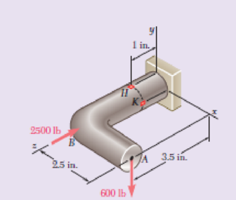
Forces are applied at points A and B of the solid cast-iron bracket shown. Knowing that the bracket has a diameter of 0.8 in., determine the principal stresses and the maximum shearing stress at (a) point H, (b) point K.
Fig. P8.72
(a)
The principal stresses and the maximum shearing stress at point H.
Answer to Problem 72RP
The maximum principal stress at point H is
The minimum principal stress at H is
The shear stress at point H is
Explanation of Solution
Given information:
The diameter (d) of the bracket is
Calculation:
Sketch the free body diagram of solid cast iron as shown in Figure 1.
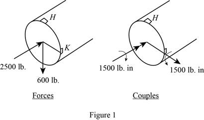
Refer to Figure 1.
Find the value of P at the section containing point H and K.
Find the shear force about y axis as follows:
Find the shear force about x axis as follows:
Find the moment about x axis as follows:
Find the moment about y axis as follows:
Find the moment about z axis as follows:
Find the value of radius (c) using the relation:
Here, d is the diameter of bracket.
Substitute
Find the area (A) of the circular section using the equation:
Here, c is the half of the diameter.
Substitute
Find the moment of inertia (I) of section using the relation:
Substitute
Find the moment of inertia (J) of section using the relation:
Substitute
Find the value of Q for semicircle using the relation:
Substitute
Determine the normal stress at point H using the relation:
Here, P is the centric force, A is the area of circular cross section, I is the moment of inertia, M is the moment, and c is the centroid distance.
Substitute
Determine the shear stress at point H using the relation:
Here, T is the Torque and J is the polar moment of inertia.
Substitute
Sketch the stresses at point H as shown in Figure 2.
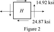
Find the average
Here, normal stress at point H.
Substitute
Find the R using the relation:
Here, shear stress at point H.
Substitute
Determine the maximum principal stress
Substitute
Thus, the maximum principal stress at point H is
Determine the minimum principal stress
Substitute
Thus, the minimum principal stress at H is
Determine the maximum shear stress at point H using the relation:
Here,
Substitute
Thus, the shear stress at point H is
(b)
The principal stresses and the maximum shearing stress at point K.
Answer to Problem 72RP
The maximum principal stress at point K is
The minimum principal stress at K is
The shear stress at point K is
Explanation of Solution
Calculation:
Determine the normal stress at point K using the relation:
Substitute
Determine the shear stress at point K using the relation:
Substitute
Sketch the stresses at point K as shown in Figure 3.
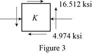
Find the average
Here, normal stress at point H.
Substitute
Find the R using the relation:
Here, shear stress at point H.
Substitute
Determine the maximum principal stress
Substitute
Thus, the maximum principal stress at point K is
Determine the minimum principal stress
Substitute
Thus, the minimum principal stress at K is
Determine the maximum shear stress at point K using the relation:
Here,
Substitute
Thus, the shear stress at point K is
Want to see more full solutions like this?
Chapter 8 Solutions
EBK MECHANICS OF MATERIALS


- 19. knowing that a force P of magnitude 75 N is applied to the pedestal shown, determine (a) the diameter of the pin at C for which the average shearing stress in the pin is 40 MPa, (b) the corresponding bearing stress in the pedestal at C, (c) the corresponding bearing stress in each support bracket at C. 75 mm 9 mm - 300 mm- B 125 mm D 5 mmarrow_forwardProblem 4 The steel pipe AB has a 102-mam outer diameter and a 6-mm wall thickness. Knowing that arm CD is rigidly attached to the pipe, determine the principal stresses and the maximum shearing stress at point K. And then show stress on Mohr's circle. 200 mm 6 mm B H D 51 mm 150 mm xarrow_forwardA steel pipe of 300-mm outer diameter is fabricated from an 8-mm-thick plate by welding along a helix that forms an angle of 20° with a plane perpendicular to the axis of the pipe. Knowing that a 250-kN axial force P and a 12-kN-m torque T. each directed as shown, are applied to the pipe, determine the normal and in-plane shearing stresses in directions, respectively, normal and tangential to the weld. T The normal stress is - The shear stress is- Weld 20⁰ 8 mm MPa MPa.arrow_forward
- SECTION B(1) Question 1 The bell crank CBA is connected to a pin support B in double shear with 8-mm diameter pin B and to the 10-mm diameter rod CD. Knowing that the ultimate shearing stress is 110 MPa for the steel used in pin B and the ultimate normal stress is 230 MPa for the steel used in rod CD. Determine the maximum vertical force P that can be applied if an overall factor of safety of 1.5 is desired. 45% 300 mm B Figure 1 -450 mm-arrow_forwardA steel pipe of 400-mm outer diameter is fabricated from 10-mm-thick plate by welding along a helix that forms an angle of 20°with a plane perpendicular to the axis of the pipe. Knowing that the maximum allowable normal and shearing stresses in the directions respectively normal and tangential to the weld are σ = 60 MPa and τ = 36 MPa, determine the magnitude P of the largest axial force that can be applied to the pipe.arrow_forwardFor the state of stress shown, it is known that the normal and shearing stresses are directed as shown and that σx= 14 ksi, σy= 9 ksi, and σmin= 5 ksi. Determine (a) the orientation of the principal planes, (b) the principal stress σmax, (c) the maximum in-plane shearing stressarrow_forward
- Problem 2. Three loads are applied to the short rectangular post shown In Fig. 2(a). The cross- sectional dimensions of the post are shown in Fig. 2(b). Determine: Me (a) The normal and shear stresses and points H and K; (b) The principal stresses and maximum in-plane shear stress at point H, and show the orientation of theses stresses in an appropriate sketch. No. M2 y 50 mm 210 kN %3D 120 mm (Naー 75 mm K 65 kN 30 mm 95 kN 160 mm 150 mm 30 mm Y-axis is the w to the sectin paimt Hond E امقره Fig. 2(b) 文 Section Proputics A= 120 X160=19200 mm Lx=160 - 40960000 mm-4094r L= 160x128 5KNス50 m-) %3D %3D = 23040000mm'= 23; 40Xlʻmm7 Int Faicesarrow_forwardFor the state of stress shown, Using Mohr's circle. determine (a) the principal stresses; and (b) the maximum in-plane shear stress. Show the results on properly oriented elements. 8 ksi 6 ksi 4 ksi FIG. P8.58arrow_forwardAn open-link chain is obtained by bending low-carbon steel rods of 0.5-in. diameter into the shape shown (Fig. ). Knowing that the chain carries a load of 160 lb, determine (a) the largest tensile and compressive stresses in the straight portion of a link, (b) the distance between the cen-troidal and the neutral axis of a cross sectionarrow_forward
- Prob.6: [2.53] A rod consisting of two cylindrical portions AB and BC is restrained at both ends. Portion AB is made of brass (Es =105 GPa , ab= 20.9 x 10⁶ /"C) and portion AB is made of aluminum (Ea =72 GPa , a.= 23.9 x 10⁻⁶ /C). Knowing that the rod is initially unstressed, determine (a) the normal stresses induced in portions AB and BC by a temperature rise of 42°C, (b) the corresponding deflection of point B. A 60-mm diameter 1.1 m - 40-mm diameter 1.3 m Carrow_forwardA spherical gas container made of steel has a 20-ft outer diameter and a wall thickness of 7/16 in. Knowing that the internal pressure is 75 psi, determine the maximum normal stress and the maximum shearing stress in the container.arrow_forwardProblem 8.5 A circular ring is subjected to a pull of 15 kN. The ring is of T-section as shown in Fig. 8.12 and the internal radius is 10 cm. Determine the maximum and minimum stresses in the ring. 2cm 12cm 10cm 2 cm Fig. 8.12arrow_forward
 Elements Of ElectromagneticsMechanical EngineeringISBN:9780190698614Author:Sadiku, Matthew N. O.Publisher:Oxford University Press
 Mechanics of Materials (10th Edition)Mechanical EngineeringISBN:9780134319650Author:Russell C. HibbelerPublisher:PEARSON
 Thermodynamics: An Engineering ApproachMechanical EngineeringISBN:9781259822674Author:Yunus A. Cengel Dr., Michael A. BolesPublisher:McGraw-Hill Education
 Control Systems EngineeringMechanical EngineeringISBN:9781118170519Author:Norman S. NisePublisher:WILEY
 Mechanics of Materials (MindTap Course List)Mechanical EngineeringISBN:9781337093347Author:Barry J. Goodno, James M. GerePublisher:Cengage Learning
 Engineering Mechanics: StaticsMechanical EngineeringISBN:9781118807330Author:James L. Meriam, L. G. Kraige, J. N. BoltonPublisher:WILEY