
Concept explainers
Videos
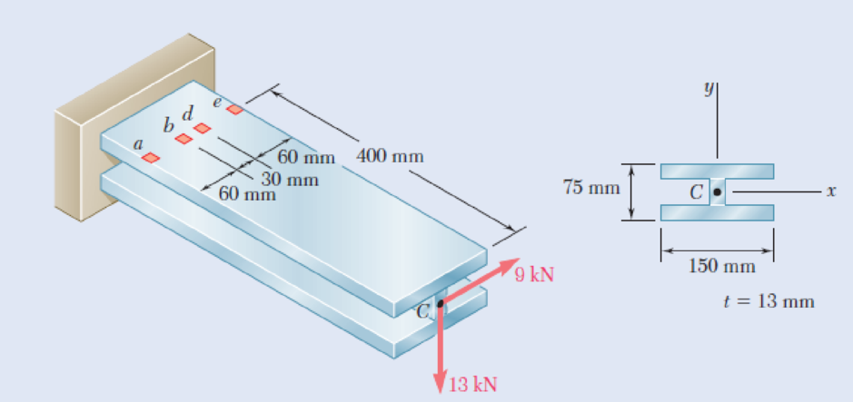
Three steel plates, each 13 mm thick, are welded together to form a cantilever beam. For the loading shown, determine the normal and shearing stresses at points d and e.
Fig. P8.53 and P8.54
The normal and shearing stress at point a and b.
Answer to Problem 54P
The normal stress at point d is
The shear stress at point d is
The normal stress at point e is
The shear stress at point e is
Explanation of Solution
Given information:
The thickness (t) of the steel plate is
Calculation:
Refer to Figure P8.51 in the textbook.
Forces at H are as follows:
The force in x direction,
The force in y direction,
The force in z direction,
Moments at H are as follows:
Find the moment about x axis as follows:
Find the moment about y axis as follows:
At point A:
Sketch the I section as shown in Figure 1.
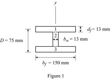
Refer to Figure 1.
Find the centroid section
Find the centroid section
Find the area of the section using the relation:
Here, b is the width and d is the depth of the flange and web respectively.
Refer to Figure 1.
Substitute
Find the moment of inertia
Substitute
Find the moment of inertia
Substitute
At point d:
Sketch the I section for point b as shown in Figure 2.
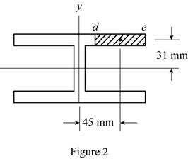
Refer to Figure 2.
Find the area of section (A) as follows:
Substitute
Refer to Figure 2.
The centroid of the
The centroid of the
Find the first moment area
Substitute
Find the first moment area
Substitute
Find the first moment area
The point e is located at edge. Since
The point e is located at edge. Since
Determine the normal stress at point d using the relation:
Here,
Substitute
Thus, the normal stress at point d is
Determine the shear stress at point a due to
Substitute
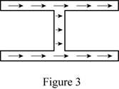
Sketch the horizontal direction of shear stress as shown in figure 3.
Determine the shear stress at point a due to
Substitute
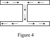
Sketch the vertical direction of shear stress as shown in figure 4.
Find the shear stress at point d using superposition method.
Thus, the shear stress at point d is
Determine the normal stress at point e using the relation:
Substitute
Thus, the normal stress at point b is
Determine the shear stress at point e using the relation:
The point e is located on edge.
The shear stress at point e is zero.
Want to see more full solutions like this?
Chapter 8 Solutions
EBK MECHANICS OF MATERIALS


- An open-link chain is obtained by bending low-carbon steel rods of 0.5-in. diameter into the shape shown (Fig. ). Knowing that the chain carries a load of 160 lb, determine (a) the largest tensile and compressive stresses in the straight portion of a link, (b) the distance between the cen-troidal and the neutral axis of a cross sectionarrow_forwardKnowing that the average normal stress in member EF of the Pratt bridge truss shown must not exceed 8.36 ksi for the given loading, determine the cross-sectional area (in sq. in) of this member that will yield the most economical and safe design if h = 14.2 ft and P = 87.28 kips.arrow_forwardProblem 6.1 A cantilever beam is subject to an end force of 15 kN inclined at 15° to the horizontal axis of the beam. The beam is 150 mm long with a rectangular section 50 mm wide x 25 mm deep. Determine the net stress distribution across the fixed end section.arrow_forward
- 8.49 A 40-kN axial load is applied to a short wooden post that is sup- ported by a concrete footing resting on undisturbed soil. Deter- mine (a) the maximum bearing stress on the concrete footing, (b) the size of the footing for which the average bearing stress in the soil is 145 kPa. |P = 40 kN 120 mm 100 mm Fig. P8.49arrow_forwardA timber beam AB of length L and rectangular cross section carries a single concentrated load P at its midpoint C. (a) Show that the ratio Tm/ m of the maximum values of the shearing and normal stresses in the beam is equal to h/2L, where h and L are, respectively, the depth and the length of the beam. (b) Determine the depth h and the width b of the beam, knowing that L = 2 m, P = 40 kN, 7m = 960 kPa, and om = 12 MPa.arrow_forwardQI/Beams AB Problems, BC, and CD have the cross section shown and are pin-connected at B and C. Knowing that the allowable normal stress is +110 MPa in tension and -150 MPa in compression, (a) determine the largest permissible value of P (b) determine distance a. 12.5 mm -200 mm- 150 mm 24 m 2.4 m 2.4 m --l|- 12.5 mmarrow_forward
- Straight rods of 0.30-in. diameter and 200-ft length are sometimes used to clear underground conduits of obstructions or to thread wires through a new conduit. The rods are made of high-strength steel and, for storage and transportation, are wrapped on spools of 5-ft diameter. Assuming that the yield strength is not exceeded, determine (a) the maximum stress in a rod, when the rod, which was initially straight, is wrapped on the spool, (b) the corresponding bending moment in the rod. Use E= 29 * 106 psi.arrow_forward7. A constructed beam ACB has a cross section of 1.5in X 1.5 in supported by a column CE having a cross section of 1in X 1in. Assuming that the allowable stresses for the connecting bolt for point C is 24 ksi for shearing and 30 ksi for bearing, determine the minimum diameter of the bolt required in Inches. 10 3A 3tarrow_forwardAn elastomeric bearing (G=130 psi) is used to support a bridge girder as shown to provide flexibility during earthquakes. The beam must not displace more than 38 in. when a 5-kip lateral load is applied as shown. Knowing that the maximum allowable shearing stress is 60 psi, determine (a) the smallest allowable dimension b, (b) the smallest required thickness a.arrow_forward
- QI/Beams AB Problems, BC, and CD have the cross section shown and are pin-connected at B and C. Knowing that the allowable normal stress is +110 MPa in tension and -150 MPa in compression, (a) determine the largest permissible value of P (b) determine distance a. 12.5 mm - 200 mm- 150 mm 24 m 24 m 24 m 125 mmarrow_forwardKnowing that the average normal stress in member EF of the Pratt bridge truss shown must not exceed 8.56 ksi for the given loading, determine the cross-sectional area (in sq. in) of this member that will yield the most economical and safe design if h = 14.3 ft and P = 89.28 kips. detailed answer pls, need answer asaparrow_forwardProblem 7.1 The flywheel of an engine is 6 m in diameter. The maximum allowable stress in the material of the flywheel is 8 MPa. Cal- culate the maximum speed at which the flywheel can be run if the den- sity of the material of the flywheel is 7800 kglm³.arrow_forward
 Elements Of ElectromagneticsMechanical EngineeringISBN:9780190698614Author:Sadiku, Matthew N. O.Publisher:Oxford University Press
 Mechanics of Materials (10th Edition)Mechanical EngineeringISBN:9780134319650Author:Russell C. HibbelerPublisher:PEARSON
 Thermodynamics: An Engineering ApproachMechanical EngineeringISBN:9781259822674Author:Yunus A. Cengel Dr., Michael A. BolesPublisher:McGraw-Hill Education
 Control Systems EngineeringMechanical EngineeringISBN:9781118170519Author:Norman S. NisePublisher:WILEY
 Mechanics of Materials (MindTap Course List)Mechanical EngineeringISBN:9781337093347Author:Barry J. Goodno, James M. GerePublisher:Cengage Learning
 Engineering Mechanics: StaticsMechanical EngineeringISBN:9781118807330Author:James L. Meriam, L. G. Kraige, J. N. BoltonPublisher:WILEY