
Concept explainers
Videos
(a)
The normal stress
(a)
Answer to Problem 97P
The normal stress
Explanation of Solution
Given information:
The state of plane stress components are
The uniaxial tension for the aluminum alloy is
The uniaxial compression for the aluminum alloy is
Calculation:
Calculate the average normal stress
Substitute
Calculate the value of
Substitute
Calculate principal stresses
Substitute
Hence, stress point lies in the first quadrant.
Sketch the Mohr’s criterion for the machine component as shown in Figure 1.
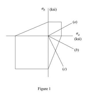
Refer to Figure 1.
The principal stresses for (a) in the first quadrant of boundary.
Calculate the value of
Substitute
Therefore, the normal stress
(b)
The normal stress
(b)
Answer to Problem 97P
The normal stress
Explanation of Solution
Given information:
The state of plane stress components are
The uniaxial tension for the aluminum alloy is
The uniaxial compression for the aluminum alloy is
Calculation:
Calculate the average normal stress
Substitute
Calculate the value of
Substitute
Calculate principal stresses
Substitute
Hence, stress point lies in the forth quadrant.
Refer to Figure 1.
The principal stresses for (b) in the forth quadrant of boundary.
Calculate the value of
Substitute
Therefore, the normal stress
(c)
The normal stress
(c)
Answer to Problem 97P
The normal stress
Explanation of Solution
Given information:
The state of plane stress components are
The uniaxial tension for the aluminum alloy is
The uniaxial compression for the aluminum alloy is
Calculation:
Calculate the average normal stress
Substitute
Calculate the value of
Substitute
Calculate principal stresses
Substitute
Hence, stress point lies in the forth quadrant.
Refer to Figure 1.
The principal stresses for (b) in the forth quadrant of boundary.
Calculate the value of
Substitute
Therefore, the normal stress
Want to see more full solutions like this?
Chapter 7 Solutions
EBK MECHANICS OF MATERIALS


- A 20 mm diameter steel rod passes concentrically through a bronze tube (200+SN) mm long, 50 mm external diameter and 40 mm internal diameter. The ends of the steel rod are threaded and provided with nuts and washers which are adjusted initially so that there is no end play at 25°C.. 1. Assuming that there is no change in the thickness of the washers, if the stress produced in the steel is (200+SN) MN/m2 when one of the nuts is tightened, the pitch of the thread being 1 mm. Find the number of turns for the nut and stress in bronze tube.2. If the temperature of the steel and bronze is then raised to 4O°C find the changes that will occur in the stresses in both materials. The coefficient of linear expansion per C is 10 x10-6 for steel and 17 x10-6 for bronze. E for steel = 210 GN/m2. E %3D for bronze = 100 GN/m2.. Note: SN = %3D Student number Student Number =32arrow_forwardProblem #6. A state of plane stress is shown b.) Determine the maximum in plane shear stress, in ksi Y т 6,000 psi 8,000 psi 4,000 psiarrow_forward60 MPa PROBLEM 7.3 45 MPa For the given state of stress, determine the normal and shearing stresses exerted on the oblique face of the shaded triangular element shown. Use a method of 120 MPA analysis based on the equilibrium of that element, as was done in the 70° derivations of Sec. 7.2. O=14.19 MPa T = 15.19 MPaarrow_forward
- A draw bar between a tractor and a trailer is made from a length of steel with a rectangular cross-section 100 mm by 12 mm. The load is transmitted to the bar via a pin through a 25 mm diameter hole at each end as shown in Fig. 4c. for 100 Fig. 4c If the load P in the bar is 100 kN, determine the following: The stress at the section X-X, shown in Fig. 4c. i (6 marks) ii The stress at the section Y-Y, shown in Fig. 4c. (5 marks)arrow_forwardA 6" diameter pulley attached to a 1" diameter shaft of 2" length is supporting a load of 2000 lb. Determine the magnitude and location of the highest bending and torsional stresses in the 1" diameter shaft.arrow_forwardQuestion 1 Not yet answered Marked out of 2.00 P Flag question the bar shown is subjected to uniform tensile stresses along the x and y axes of a magnitude 676 MPa. if the length a = 45 mm and the length b = 34 mm if the modulus of elasticity E = 120 GP, and the Poisson's ratio is 0.3 then, its new length b is mm a a. 34.1915 b. 34.0575 C. 168.0733 d. 34.1341arrow_forward
- A lightweight lever consists of a 0.8m solid bar rigidly mounted to a large structure and a 0.5m solid lever welded to the solid bar. Using the loading indicated and assuming the material has a Young's Modulus of 200 GPa and a shear modulus of 86 GPa, calculate: (a) the maximum stress at Point A on the Cross-section a-a, (b) the vertical displacement of the knob when the load is applied relative to Cross-section a-a. B C 50 mm Section ad a 0.8 m 0.5 m 100 N 38 mm Focusarrow_forwardA composite cube with 40-mm sides and the properties shown is made with glass polymer fibers aligned in the x direction. The cube is constrained against deformations in the y and z directions and is subjected to a tensile load of 65 kN in the x direction. Determine (b) the stresses a, a, and o,. E = 50 GPa E, = 15.2 GPa E.= 15.2 GPa = 0.254 Lay= 0.254 Vay = 0.428 %3D The stresses o,, oy, and o, are and MPa, respectively. (up to 1st decimal place please).arrow_forward2. (a) A steel cylinder of 60 mm inner radius and 80 mm outer radius is subjected to an internal pressure of 30 MNm ². Determine the resulting hoop stress values at the inner and outer surfaces and graphically represent (sketch) the general form of hoop stress variation through the thickness of the cylinder wall. (b) (c) The cylinder in (a) is to be used as a shrink-fitted sleeve to strengthen a hydraulic cylinder manufactured of the same steel. The cylinder bore radius is 40 mm. When the hydraulic cylinder is not subjected to internal pressure, the interference pressure generated due to the shrink fit alone is 30 MNm2. Note: This is the same value of pressure as in the problem analysed in part (a). Determine the resulting hoop stress values at the inner and outer walls of the inner cylinder. Graphically represent the general form of hoop stress variation through the wall thickness in the combination indicating the key values as calculated in parts (a) and (b). (d) If the Young's…arrow_forward
- Fig. 2 4. A steel shaft of diameter 50 mm and length 1.2 m (E = 210 GPa and v = 0.3) is loaded with multiple force system. At a point in the shaft, the state of stress relative to the x, y, z coordinate system was found to be: [600 0 T = 0 320 MPa -480 (a) Draw a cube element showing the stress components on each coordinate face (Hint: No vector lines for zero stresses; Warning: A stress element without reference axes will receive zero point). (b) From the given stress tensor, determine the values of (i) octahedral normal stress (Goct) and (ii) octahedral shear stress (toct). (c) From your answer in (b), determine (i) dilatational strain energy Udilat '); and (ii) deviatoric strain energy (Udist). (d) Find the total strain energy at the point.arrow_forward12. A single strain gage is cemented to solid 96-mm-diameter aluminum shaft at an angle B = 20° with a line parallel to the axis of the shaft. Knowing that G = 27 GPa, determine the torque T corresponding to a gage reading of 400u. 48 mm Figure P12arrow_forwardProblem #6a A state of plane stress is shown a.) Determine the maximum principle stress, in ksi 6,000 psi 8,000 psi 4,000 psiarrow_forward
 Elements Of ElectromagneticsMechanical EngineeringISBN:9780190698614Author:Sadiku, Matthew N. O.Publisher:Oxford University Press
 Mechanics of Materials (10th Edition)Mechanical EngineeringISBN:9780134319650Author:Russell C. HibbelerPublisher:PEARSON
 Thermodynamics: An Engineering ApproachMechanical EngineeringISBN:9781259822674Author:Yunus A. Cengel Dr., Michael A. BolesPublisher:McGraw-Hill Education
 Control Systems EngineeringMechanical EngineeringISBN:9781118170519Author:Norman S. NisePublisher:WILEY
 Mechanics of Materials (MindTap Course List)Mechanical EngineeringISBN:9781337093347Author:Barry J. Goodno, James M. GerePublisher:Cengage Learning
 Engineering Mechanics: StaticsMechanical EngineeringISBN:9781118807330Author:James L. Meriam, L. G. Kraige, J. N. BoltonPublisher:WILEY