
Concept explainers
Videos
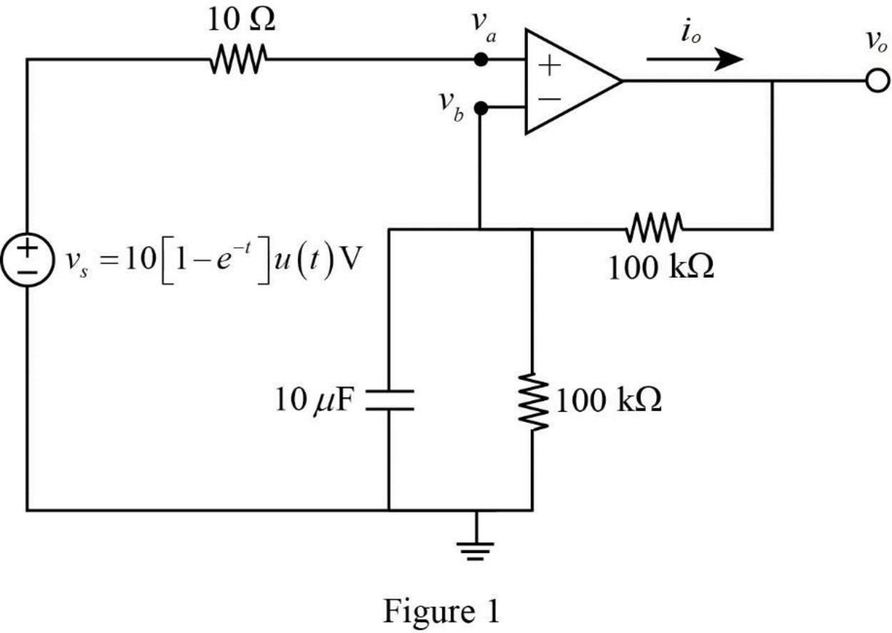
In the circuit of Fig. 7.140, find vo and io, given that vs = 10[1 – e–t]u(t) V.
![Chapter 7, Problem 75P, In the circuit of Fig. 7.140, find vo and io, given that vs = 10[1 et]u(t) V.](http://dev-ingestion-image-output.s3-website-us-east-1.amazonaws.com/9780078028229/Chapter-7/images/28229-7-75p-question-digital_image_001.png)
Find the output voltage
Answer to Problem 75P
The output voltage
Explanation of Solution
Given data:
Refer to Figure 7.140 in the textbook.
The value of capacitance
The source voltage
Formula used:
Write the general expression for the unit step function.
Calculation:
The given Figure 7.140 is redrawn as shown in Figure 1.
The given source voltage is,
Apply the unit step function in equation (1) to equation (2).
Consider the voltage at the non-inverting terminal as
For
Since the source voltage
For
The voltage,
On differentiating the equation (3).
In Figure 1, apply Kirchhoff’s current law at node
Substitute
Rearrange the equation as follows,
Simplify the equation as follows,
Apply the unit step function in equation (1) to equation (5).
The output current
Substitute
Convert the unit A to
Conclusion:
Thus, the output voltage
Want to see more full solutions like this?
Chapter 7 Solutions
Fundamentals of Electric Circuits


- 2. 7.8 The switch in the circuit has been open for a long time. The initialcharge on the capacitor is zero. At t=0 the switch is closed. Find theexpression for 2. b)v(t) for t≥0+.arrow_forwardConsider the following circuit in which the inductor current and the capacitor voltage are equal to zero at t = 0 s. Find the value of v at t = 2 s.arrow_forwardA 12 volt battery is connected to a simple series circuit where the inductance is 1/2 henrio and the resistance is 10 ohms. Determine the current if the initial current is 0. topic: ORDINARY DIFFERENTIAL EQUATIONSarrow_forward
- 7.4 The switch in the circuit shown has been closed for a long timebefore being opened at t=0.1. a) Find vo(t) for t≥0.arrow_forwardIn the circuit below, the switch is closed at t=0 s. It is known that the voltage across the capacitor at t=0.2 s is Vc( t = 0.2 ) = 10.31 V. In this case, what will be the voltage Vc( t = 0.1 ) of the capacitor at t=0.1 s? Calculate.arrow_forwardThe switch in the circuit shown in Fig. 7.6 has been closed for a long timebefore it is opened at t=0. Find 4. the percentage of the total energy stored in the 2 H inductor that isdissipated in the 10 Ω resistor.arrow_forward
- Find Uc for t > 0 in the circuitarrow_forwardkindly help me with this problem thank you so much! Instructions: Evaluate and Show neat, logical, and complete solution.show final answers in four decimal places. 3. A 20 μF capacitor in an audio amplifier produces a voltage drop of 5 V at 1kHz. Find the current passed by the capacitor.arrow_forwardThe circuit parameters in the circuit are R=4800 Ω, L=64 mH, C=4 nF, and vg=−72 V.1. Express vo(t) numerically for t≥0.2. How many microseconds after the switch opens is the inductorvoltage maximum?3. What is the maximum value of the inductor voltage?4. Repeat (a)–(c) with R reduced to 480 Ωarrow_forward
- No energy is stored in the 100 mH inductor or the 0.4μF capacitor when theswitch in the circuit shown is closed. Find vC(t) for t≥0arrow_forwardThe switch in the circuit below opens at t=0 after being kept in the closed position for a long time. Accordingly, which of the following is the value of v(∞)?arrow_forwardFind the energy stored in a 3 μF capacitor and v= 12 v.arrow_forward
 Introductory Circuit Analysis (13th Edition)Electrical EngineeringISBN:9780133923605Author:Robert L. BoylestadPublisher:PEARSON
 Delmar's Standard Textbook Of ElectricityElectrical EngineeringISBN:9781337900348Author:Stephen L. HermanPublisher:Cengage Learning
 Programmable Logic ControllersElectrical EngineeringISBN:9780073373843Author:Frank D. PetruzellaPublisher:McGraw-Hill Education
 Fundamentals of Electric CircuitsElectrical EngineeringISBN:9780078028229Author:Charles K Alexander, Matthew SadikuPublisher:McGraw-Hill Education
 Electric Circuits. (11th Edition)Electrical EngineeringISBN:9780134746968Author:James W. Nilsson, Susan RiedelPublisher:PEARSON
 Engineering ElectromagneticsElectrical EngineeringISBN:9780078028151Author:Hayt, William H. (william Hart), Jr, BUCK, John A.Publisher:Mcgraw-hill Education,