
Concept explainers
Videos
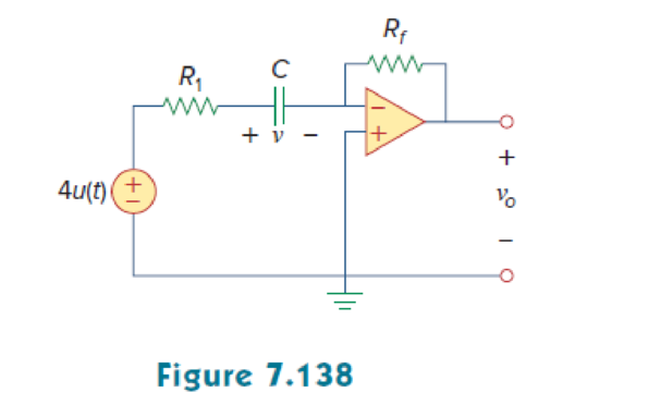
For the op amp circuit of Fig. 7.138, let R1 = 10 kΩ, Rf = 30 kΩ, C = 20 μF, and v(0) = 1 V. Find v0.
Find the output voltage
Answer to Problem 73P
The output voltage
Explanation of Solution
Given data:
Refer to Figure 7.138 in the textbook.
The value of capacitance
The source voltage
The value of resistance
The value of feedback resistance
The initial voltage v(0) or
Formula used:
Write the expression to find the time constant for an RC circuit.
Here,
C is the capacitance of the capacitor.
Write the general expression for the unit step function.
Calculation:
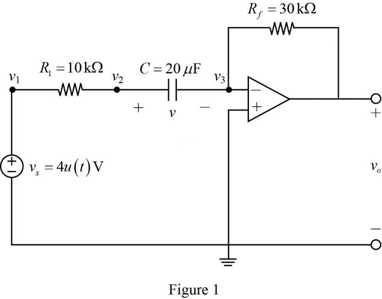
The given Figure 7.138 is redrawn as shown in Figure 1.
The given source voltage is,
Apply the unit step function in equation (2) to equation (3).
For
Since the source voltage
For
The source voltage is,
In Figure 1, apply Kirchhoff’s current law at node
In Figure 1, apply Kirchhoff’s current law at node
From Figure 1, the voltages are,
Substitute
Substitute
Rearrange the equation as follows,
The equation is similar to the equation (7.42) in the textbook.
Hence,
In Figure 1, the Thevenin resistance
Substitute
Substitute the units
Substitute 1 V for
On differentiating the above equation as follows,
Substitute
Substitute
Apply the unit step function in equation (2) to equation (9).
Conclusion:
Thus, the output voltage
Want to see more full solutions like this?
Chapter 7 Solutions
Fundamentals of Electric Circuits


- Determine the current in the inductor i (t), for t <0 and t> 0 (see attached image of the circuit)arrow_forwardThe switch in the circuit shown in Fig. 7.21 has been in position a for a longtime. At t=0, the switch moves from position a to position b. The switch is amake-before-break type; that is, the connection at position b is establishedbefore the connection at position a is broken, so the inductor current iscontinuous.5. Plot both i(t) and v(t) versus t.arrow_forwardDesign a monostable multivibrator to have a pulsewidth of 20 s and a recovery time of 5 s. Usethe circuit with ±5 V supplies.arrow_forward
- For the following circuit obtain: (a) the response v(t) for t>0, (b) the current i(t) through the inductor for t>0.arrow_forwardA 100µF capacitor is connected in series with a 150volt voltmeter that has a resistance of 1,000 ohms per volt. Calculate the reading of the voltmeter at the instant when t equals the time constant following the closing if the switch that impresses 120volts on the circuit.arrow_forwardA capacitor with a capacitance of 29 microfarads is discharged through a resistance of 36 kilo-ohms. How many milliseconds does it take for the voltage to drop to 1/e of its initial value. Here "e" is the base of natural logarithms, about 2.718 .arrow_forward
- Find the energy stored in a 3 μF capacitor and v= 12 v.arrow_forwardThe switch in the circuit seen in fig 7.54arrow_forwardA 12 volt battery is connected to a simple series circuit where the inductance is 1/2 henrio and the resistance is 10 ohms. Determine the current if the initial current is 0. topic: ORDINARY DIFFERENTIAL EQUATIONSarrow_forward
- A dc constant voltage source feeds a resistance of 2,000 kΩ in series with a 5µF capacitor. Find the time taken for the capacitor when the charge retained will be decayed to 50% of the initial value, the voltage sourcing being short circuited. Ans 11arrow_forwardPlease assist with this Matlab exercise. Image exercise 2arrow_forwardIn the circuit below, the switch is closed at t=0 s. It is known that the voltage across the capacitor at t=0.2 s is Vc( t = 0.2 ) = 10.31 V. In this case, what will be the voltage Vc( t = 0.1 ) of the capacitor at t=0.1 s? Calculate.arrow_forward
 Introductory Circuit Analysis (13th Edition)Electrical EngineeringISBN:9780133923605Author:Robert L. BoylestadPublisher:PEARSON
 Delmar's Standard Textbook Of ElectricityElectrical EngineeringISBN:9781337900348Author:Stephen L. HermanPublisher:Cengage Learning
 Programmable Logic ControllersElectrical EngineeringISBN:9780073373843Author:Frank D. PetruzellaPublisher:McGraw-Hill Education
 Fundamentals of Electric CircuitsElectrical EngineeringISBN:9780078028229Author:Charles K Alexander, Matthew SadikuPublisher:McGraw-Hill Education
 Electric Circuits. (11th Edition)Electrical EngineeringISBN:9780134746968Author:James W. Nilsson, Susan RiedelPublisher:PEARSON
 Engineering ElectromagneticsElectrical EngineeringISBN:9780078028151Author:Hayt, William H. (william Hart), Jr, BUCK, John A.Publisher:Mcgraw-hill Education,