
Calculate the current response
Answer to Problem 57P
The current response
Explanation of Solution
Given data:
Refer to Figure 7.123 in the textbook.
The value of inductance
The value of inductance
Formula used:
Write the general expression to find the current response for the RL circuit.
Here,
Write the expression to calculate the time constant for the RL circuit.
Here,
L is the inductance of the inductor.
Write the general expression for the unit step function.
Calculation:
For
The given Figure 7.123 is redrawn as shown in Figure 1. At this condition, the inductor reaches steady state and acts like a short circuit to DC.

In Figure 1, apply Kirchhoff’s current law at node
Simplify the equation as follows,
Now find the initial inductor current
Substitute
Now find the initial inductor current
Substitute
For
Figure 2 shows the modified circuit diagram when the switch is kept in closed position.
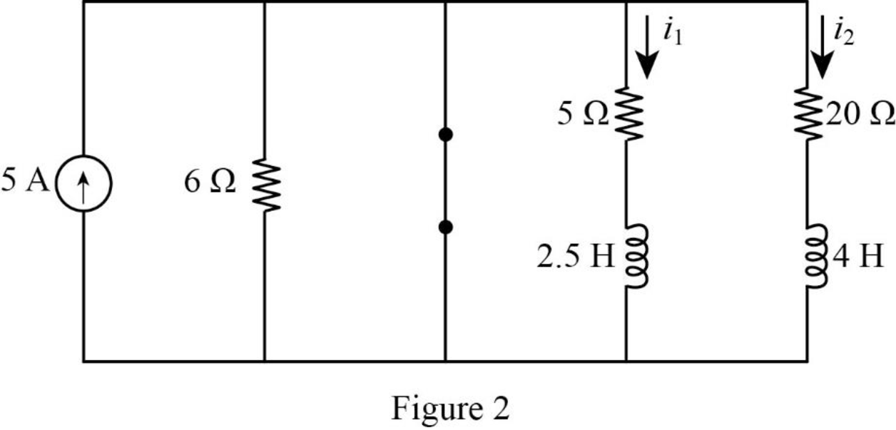
Consider the value of resistances
In Figure 2, the switch is closed so that the energies in the inductance
The current response
The time constant in equation (6) can be rewritten as like in equation (2) as follows.
Substitute
Substitute the units
Substitute
Apply the unit step function in equation (3) to equation (9).
The current response
The time constant in equation (10) can be rewritten as like in equation (2) as follows.
Substitute
Substitute the units
Substitute
Apply the unit step function in equation (3) to equation (13).
Convert the unit A to mA.
Conclusion:
Thus, the current response
Want to see more full solutions like this?
Chapter 7 Solutions
Fundamentals of Electric Circuits

- 4. 7.4 The switch shown has been open for a long time beforeclosing at t=0 5. 6. f) Write the expression for vL(t) for t≥0+.arrow_forward4.2) Build a circuit for X by referring to the equation you have derived in 4.1. ( first image below) Take a picture of your circuit and attach it in the space provided. Attach your circuit for X here: ii) Does the behavior of your circuit match the truth table? If not, what might be wrong?arrow_forwardFind the complete response of v and I for the t >0 in the circuitarrow_forward
- The switch in the circuit shown in Fig. 7.6 has been closed for a long timebefore it is opened at t=0. Find 3. vo(t) for t≥0+,arrow_forwardThe switch in the circuit shown in Fig. 7.21 has been in position a for a longtime. At t=0, the switch moves from position a to position b. The switch is amake-before-break type; that is, the connection at position b is establishedbefore the connection at position a is broken, so the inductor current iscontinuous.5. Plot both i(t) and v(t) versus t.arrow_forward7.4 The switch in the circuit shown has been closed for a long timebefore being opened at t=0.1. a) Find vo(t) for t≥0.arrow_forward
- After being open for a long time, the switch shown in the circuit below closes at t = 0 Find VR(t) for t > 0arrow_forward1. 7.1 The switch in the circuit shown has been closed for a long time andis opened at t=0.1. a) Calculate the initial value of i.arrow_forwardAn LTI system is considered.The response of the system to x1(t) is y1(t). Then find and sketch the response of the system to x2(t) and x3(t).arrow_forward
- 1)The function L (x, y, z) given the truth table a) Write algebraically in the 1st canonical and 2. canonical expansions separately,b) Write in numerical form in the 1st canonical and 2.canonical expansions form,c) Perform the function with 2x1 MUX as y input is the selection input. 2)Obtain 4x1 MUX by using 2x1 MUX. Write down the table.arrow_forwardFor the circuit shown, the switch was open for a long time, then it is closed at t=0. Find Vc(t) for t>0. *arrow_forward"The switch in the circuit shown has been closed for a long time.At t=0 the switch opens and remains open." 4. What is the expression for io(t) when t≥0?arrow_forward
 Introductory Circuit Analysis (13th Edition)Electrical EngineeringISBN:9780133923605Author:Robert L. BoylestadPublisher:PEARSON
 Delmar's Standard Textbook Of ElectricityElectrical EngineeringISBN:9781337900348Author:Stephen L. HermanPublisher:Cengage Learning
 Programmable Logic ControllersElectrical EngineeringISBN:9780073373843Author:Frank D. PetruzellaPublisher:McGraw-Hill Education
 Fundamentals of Electric CircuitsElectrical EngineeringISBN:9780078028229Author:Charles K Alexander, Matthew SadikuPublisher:McGraw-Hill Education
 Electric Circuits. (11th Edition)Electrical EngineeringISBN:9780134746968Author:James W. Nilsson, Susan RiedelPublisher:PEARSON
 Engineering ElectromagneticsElectrical EngineeringISBN:9780078028151Author:Hayt, William H. (william Hart), Jr, BUCK, John A.Publisher:Mcgraw-hill Education,