
PEARSON ETEXT ENGINEERING MECH & STATS
15th Edition
ISBN: 9780137514724
Author: HIBBELER
Publisher: PEARSON
expand_more
expand_more
format_list_bulleted
Concept explainers
Videos
Textbook Question
Chapter 7, Problem 50P
If L = 9 m, the beam will fail when the maximum shear force is Vmax = 5kN or the maximum bending moment is Mmax = 2kN · m. Determine the magnitude M0 of the largest couple moments it will support.
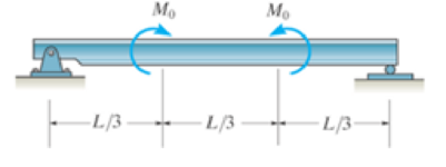
Probs. 7–49/50
Expert Solution & Answer
Want to see the full answer?
Check out a sample textbook solution
Students have asked these similar questions
Determine the internal shear force and moment acting on point C
7-8. Determine the internal shear force and moment
acting at point C in the beam.
900 lb-ft
-3 ft-
6 ft
Vc = 0
Mc = 8100 lb*ft
500 lb/ft
+
Prob. 7-8
6 ft
B
900 lb-ft
-3 ft-
I1-47. The beam is made from three boards nailed
together as shown. If the moment acting on the crass section
is M= 600 N- m, determine the maximum bending stress in
the beam. Sketch a three-dimensional view af the stress
distribution and cover the cross section.
25 mm
150 mm
-20 mm
200 mim M- 600 Nm
20
The shaft is supported by a journal bearing at A and a thrust
bearing at B. Determine the normal force, shear force and moment
at a section passing through (a) point C, which is just to right of
bearing at A, and (b) point D, which is just to the left of the Force F2.
Given:
F1 =
= 2.5 kip
F2 = 3 kip
lb
W = 75
ft
-
b = 12 ft
c = 2 ft
a = 6 ft
F2
D
a
b
Chapter 7 Solutions
PEARSON ETEXT ENGINEERING MECH & STATS
Ch. 7 - Determine the normal force, shear force, and...Ch. 7 - Determine the normal force, shear force, and...Ch. 7 - Determine the normal force, shear force, and...Ch. 7 - Determine the normal force, shear force, and...Ch. 7 - Determine the normal force, shear force, and...Ch. 7 - Determine the normal force, shear force, and...Ch. 7 - Determine the shear force and moment at points C...Ch. 7 - The pliers are used to grip the tube at B. If a...Ch. 7 - Determine the distance a as a fraction of the...Ch. 7 - The cable will fail when subjected to a tension of...
Ch. 7 - Determine the distance a between the bearings in...Ch. 7 - The cantilevered rack is used to support each end...Ch. 7 - Rod AB is fixed to a smooth collar D, which slides...Ch. 7 - Prob. 22PCh. 7 - Determine the normal force, shear force, and...Ch. 7 - The distributed loading W = W0 sin , measured per...Ch. 7 - Solve Prob. 7-39 for = 120. Probs. 739/40Ch. 7 - Determine the x, y, z components of force and...Ch. 7 - Determine the x, y, z components of internal...Ch. 7 - Determine the shear and moment as a function of x,...Ch. 7 - Determine the shear and moment as a function of x,...Ch. 7 - Determine the shear and moment as a function of x,...Ch. 7 - Determine the shear and moment as a function of x,...Ch. 7 - Determine the shear and moment as a function of x,...Ch. 7 - Determine the shear and moment as a function of x,...Ch. 7 - Draw the shear and moment diagrams for the shaft...Ch. 7 - Draw the shear and moment diagrams for the beam...Ch. 7 - Draw the shear and moment diagrams for the beam...Ch. 7 - Draw the shear and moment diagrams for the...Ch. 7 - Draw the shear and moment diagrams of the beam (a)...Ch. 7 - If L = 9 m, the beam will fail when the maximum...Ch. 7 - Draw the shear and moment diagrams for the beam....Ch. 7 - Draw the shear and moment diagrams for the beam....Ch. 7 - The shaft is supported by a smooth thrust bearing...Ch. 7 - Draw the shear and moment diagrams for the beam....Ch. 7 - Prob. 58PCh. 7 - Prob. 59PCh. 7 - The shaft is supported by a smooth thrust bearing...Ch. 7 - Draw the shear and moment diagrams for the beam....Ch. 7 - Prob. 65PCh. 7 - Draw the shear and moment diagrams for the beam....Ch. 7 - Draw the shear and moment diagrams for the beam....Ch. 7 - Draw the shear and moment diagrams for the beam....Ch. 7 - Draw the shear and moment diagrams for the beam....Ch. 7 - Draw the shear and moment diagrams for the beam....Ch. 7 - Draw the shear and moment diagrams for the beam....Ch. 7 - Draw the shear and moment diagrams for the beam....Ch. 7 - Draw the shear and moment diagrams for the beam....Ch. 7 - Draw the shear and moment diagrams for the beam....Ch. 7 - Draw the shear and moment diagrams for the beam....Ch. 7 - Draw the shear and moment diagrams for the beam....Ch. 7 - Draw the shear and moment diagrams for the beam....Ch. 7 - Draw the shear and moment diagrams for the beam....Ch. 7 - The cable supports the three loads shown....Ch. 7 - Prob. 95PCh. 7 - Determine the tension in each segment of the cable...Ch. 7 - Prob. 97PCh. 7 - The cable supports the loading shown. Determine...Ch. 7 - The cable supports the three loads shown....Ch. 7 - The cable supports the three loads shown....Ch. 7 - Determine the maximum uniform loading w, measured...Ch. 7 - The cable is subjected to a uniform loading of w =...Ch. 7 - If x = 2 ft and the crate weighs 300 lb, which...Ch. 7 - If yB = 1.5 ft. determine the largest weight of...Ch. 7 - The cable supports a girder which weighs 850...Ch. 7 - If the pipe has a mass per unit length of 1500...Ch. 7 - Prob. 110PCh. 7 - The cable will break when the maximum tension...Ch. 7 - Prob. 2RPCh. 7 - Prob. 3RPCh. 7 - Prob. 4RPCh. 7 - Draw the shear and moment diagrams for the beam....Ch. 7 - A chain is suspended between points at the same...
Knowledge Booster


Learn more about
Need a deep-dive on the concept behind this application? Look no further. Learn more about this topic, mechanical-engineering and related others by exploring similar questions and additional content below.Similar questions
- 7-11. Determine the internal normal force, shear force, and moment at points C and D of the beam. 60 lb/ft 12 ft Prob. 7-10 15 ft 40 lb/ft _B Prob. 7-11 ID -5 ft- -10 ft 690 lb 13/12arrow_forwardDetermine the internal normal force, internal shear force, and internal moment at point C. The external loading applied to the beam is the beam's weight of w per unit length. Hint: Assume the beam's weight is applied as a constant distributed load. 2/7arrow_forwardThe aluminum rod has a cross-shaped cross section. If subjected to the moment M = 8 kN x m, determine the bending stress acting at points A and B and show the results acting on volume elements located at these points. 100 mm 20 mm 100 mm B M = 8 kN-m 20 mm- 50 mm 50 mmarrow_forward
- Draw the shear force and bending moment diagrams of the cantilever beam shown using METHOD OF SECTIONS. Determine the maximum shear force and maximum bending moment. Hint: the trapezoidal load may be divided into a rectangular load and a triangular load. Express the triangular load as a function of X. C 20 kN m 2 m 8 kN B 5 kN/m 8 kN/m 3 m 6 m 15 kN/m Darrow_forwardThe beam is loaded with a uniformly varying load O at point D and maximum of 7 kN/m at the fixed support. Determine the resulting moment at the fixed support. D B 1.8 m →+ 0.8 m → 0.4 m 25 kNarrow_forward7-8. Determine the internal shear force and moment acting at point Cin the beam. 900 lb - ft 500 Ib/ft 900 Ib - ft A 61 -3 ft- Prob. 7-8arrow_forward
- The cantilever beam is supported by a fixed support at A, and subjected to the force F = 600 lb and the couple M = 2810 ft-lb. Draw the shear force and bending moment diagrams (in your homework documentation) and determine the equations for V(x) and M(r). Take a = 0 at point A. a •b C M A- В Values for dimensions on the figure are given in the following table. Note the figure may not be to scale. Variable Value a 5.2 ft b 3.9 ft Support Reactions The force reaction at A is Ib (take up as positive). The couple moment reaction at A is ft-lb (take counterclockwise as positive). Shear Force and Bending Moment Equations In section AB: V(x)- In section BC: V(x)- lb and M(x)= ft-lb. lb and 'M(x)= ft-lb.arrow_forwardB Determine the normal force, shear force, and moment at a section passing through point C. Take P = 8 kN. 0.1 m 0.5 m C A -0.75 m- -0.75 m -0.75 m-arrow_forwardDetermine the internal normal force, shear force and the moment at points Cin the simply supported beam. 3 kN/m A ma 5 kN C ism b D 1.5 m 1.5 m- 3 m Barrow_forward
- FI-6. Determine the resultant internal normal force, shear force, and bending moment at point Cin the beam. 5 KN /marrow_forwardThe magnitude of the triangular distributed load is w0 = 2 kN/m. Determine the internal forces and moment at A.arrow_forwardThe cantilevered beam has a circular cross section. If it supports a force P at its end, determine its radius y as a function of x so that it is subjected to a constant maximum bending stress sallow throughout its length.arrow_forward
arrow_back_ios
SEE MORE QUESTIONS
arrow_forward_ios
Recommended textbooks for you
 Elements Of ElectromagneticsMechanical EngineeringISBN:9780190698614Author:Sadiku, Matthew N. O.Publisher:Oxford University Press
 Mechanics of Materials (10th Edition)Mechanical EngineeringISBN:9780134319650Author:Russell C. HibbelerPublisher:PEARSON
 Thermodynamics: An Engineering ApproachMechanical EngineeringISBN:9781259822674Author:Yunus A. Cengel Dr., Michael A. BolesPublisher:McGraw-Hill Education
 Control Systems EngineeringMechanical EngineeringISBN:9781118170519Author:Norman S. NisePublisher:WILEY
 Mechanics of Materials (MindTap Course List)Mechanical EngineeringISBN:9781337093347Author:Barry J. Goodno, James M. GerePublisher:Cengage Learning
 Engineering Mechanics: StaticsMechanical EngineeringISBN:9781118807330Author:James L. Meriam, L. G. Kraige, J. N. BoltonPublisher:WILEY
Elements Of Electromagnetics
Mechanical Engineering
ISBN:9780190698614
Author:Sadiku, Matthew N. O.
Publisher:Oxford University Press
Mechanics of Materials (10th Edition)
Mechanical Engineering
ISBN:9780134319650
Author:Russell C. Hibbeler
Publisher:PEARSON
Thermodynamics: An Engineering Approach
Mechanical Engineering
ISBN:9781259822674
Author:Yunus A. Cengel Dr., Michael A. Boles
Publisher:McGraw-Hill Education
Control Systems Engineering
Mechanical Engineering
ISBN:9781118170519
Author:Norman S. Nise
Publisher:WILEY
Mechanics of Materials (MindTap Course List)
Mechanical Engineering
ISBN:9781337093347
Author:Barry J. Goodno, James M. Gere
Publisher:Cengage Learning
Engineering Mechanics: Statics
Mechanical Engineering
ISBN:9781118807330
Author:James L. Meriam, L. G. Kraige, J. N. Bolton
Publisher:WILEY
Everything About COMBINED LOADING in 10 Minutes! Mechanics of Materials; Author: Less Boring Lectures;https://www.youtube.com/watch?v=N-PlI900hSg;License: Standard youtube license