Elements Of Electromagnetics
7th Edition
ISBN: 9780190698614
Author: Sadiku, Matthew N. O.
Publisher: Oxford University Press
expand_more
expand_more
format_list_bulleted
Question

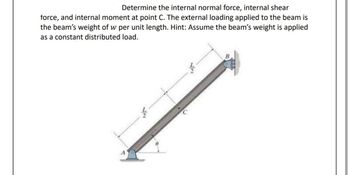
Transcribed Image Text:**Problem Statement:**
Determine the internal normal force, internal shear force, and internal moment at point C. The external loading applied to the beam is the beam’s weight of \( w \) per unit length. Hint: Assume the beam’s weight is applied as a constant distributed load.
**Diagram Explanation:**
The image shows a beam inclined at an angle \( \theta \), with two supports. The support at point A is at the bottom end of the beam, which is positioned on a flat surface. The top end of the beam is fixed to a wall at point B.
- The total length of the beam is denoted as \( L \).
- The beam is divided into two equal segments, each of length \( \frac{L}{2} \).
- Point C is located at the midpoint of the beam.
- A distributed load, indicating the beam's weight per unit length \( w \), acts along the entire length of the beam.
The problem involves calculating the internal forces and moments at the midpoint of this beam setup.
Expert Solution
This question has been solved!
Explore an expertly crafted, step-by-step solution for a thorough understanding of key concepts.
This is a popular solution
Trending nowThis is a popular solution!
Step by stepSolved in 4 steps with 10 images

Knowledge Booster
Learn more about
Need a deep-dive on the concept behind this application? Look no further. Learn more about this topic, mechanical-engineering and related others by exploring similar questions and additional content below.Similar questions
- 3arrow_forwardDetermine the magnitude of the vertical force Cy for the cantilever beam, where P = 29 kips and M = 40 kip-ft. A 3.5 ft O 21 kips O 25 kips 42 kips 18 kips 29 kips M B 6.5 ftarrow_forward1. For the simply supported beam with a T-shape cross-section as shown below, a- Draw the shear and moments diagram of the beam. b- Determine the maximum normal bending stress and specify its location. C- If the beam made from two boards determines the maximum shear stress in the glue necessary to hold the boards together along the seam where they are joined. d- Determine the shear stress at point B. 4 m 6.5 kN/m 6m- Glue 150 mm 30 mm 150 mm 30 mmarrow_forward
- If the beam is subjected to a shear force of V = 40 kN, a. Compute the shear stress at the web and flange interface b. Compute the shear stress 10 mm below the uppermost part of the cross section of the beam 200 mm 30 mm 280 mm 25 mmarrow_forwardplease casn yiu explain how to solve thisarrow_forwardDetermine the internal normal force and shear force, and the bending moment in the beam at points C and D. Assume the support at B is a roller. Point C is located just to the right of the 8-kip load.arrow_forward
- Using the area method, draw the shear force and bending moment diagrams for the beam. Don't think about the beam's weight.arrow_forward3. For the loaded beam shown below, determine the shear and moment equations and draw the shear and moment diagrams. R₁ = R₂ = 300 lb. Diagrams only without solutions will not be checked. All equations must be supported with the necessary FBDs of sections considered. M = 1200 lb-ft 2 ft- R₁ 100 lb/ft B 4 ft- E 1ft iftR₂arrow_forwardfor final answer please round off to 2 decimal places for thumbs up!arrow_forward
- A simply supported beam of span 3.0 m has a cross-section 120 mm x 180mm. If the permissible stress in the material of the beam is 10N / mm ^ 2 determine (i)maximum udl it can carry (ii) maximum concentrated load at a point I m from support it can carry. Neglect moment due to self weight.?arrow_forward3. If the beam is subjected to a shear force of V = 40 kN, a. Compute the shear stress at the web and flange interface b. Compute the shear stress 10 mm below the uppermost part of the cross section of the beam 200 mm T- 30 mm 280 mm |25 mmarrow_forwardDetermine the values of shear and moment at points where changes in loads occur using shear and moment diagram. Compute the moment of inertia of the beam cross-section about the neutral axis. Compute the maximum shear, tensile, and compressive flexural stresses. Write the moment equation of the beam. Draw the elastic curve. Concentrated Load = 350N, Triangular Load = 1700N/m Dimensions: Length = 1.0(2) = 2.0mm, Thickness = 40mm, Height = 200mm, Height - Thickness = 160mmarrow_forward
arrow_back_ios
SEE MORE QUESTIONS
arrow_forward_ios
Recommended textbooks for you
 Elements Of ElectromagneticsMechanical EngineeringISBN:9780190698614Author:Sadiku, Matthew N. O.Publisher:Oxford University Press
 Mechanics of Materials (10th Edition)Mechanical EngineeringISBN:9780134319650Author:Russell C. HibbelerPublisher:PEARSON
 Thermodynamics: An Engineering ApproachMechanical EngineeringISBN:9781259822674Author:Yunus A. Cengel Dr., Michael A. BolesPublisher:McGraw-Hill Education
 Control Systems EngineeringMechanical EngineeringISBN:9781118170519Author:Norman S. NisePublisher:WILEY
 Mechanics of Materials (MindTap Course List)Mechanical EngineeringISBN:9781337093347Author:Barry J. Goodno, James M. GerePublisher:Cengage Learning
 Engineering Mechanics: StaticsMechanical EngineeringISBN:9781118807330Author:James L. Meriam, L. G. Kraige, J. N. BoltonPublisher:WILEY

Elements Of Electromagnetics
Mechanical Engineering
ISBN:9780190698614
Author:Sadiku, Matthew N. O.
Publisher:Oxford University Press

Mechanics of Materials (10th Edition)
Mechanical Engineering
ISBN:9780134319650
Author:Russell C. Hibbeler
Publisher:PEARSON

Thermodynamics: An Engineering Approach
Mechanical Engineering
ISBN:9781259822674
Author:Yunus A. Cengel Dr., Michael A. Boles
Publisher:McGraw-Hill Education

Control Systems Engineering
Mechanical Engineering
ISBN:9781118170519
Author:Norman S. Nise
Publisher:WILEY

Mechanics of Materials (MindTap Course List)
Mechanical Engineering
ISBN:9781337093347
Author:Barry J. Goodno, James M. Gere
Publisher:Cengage Learning

Engineering Mechanics: Statics
Mechanical Engineering
ISBN:9781118807330
Author:James L. Meriam, L. G. Kraige, J. N. Bolton
Publisher:WILEY