
PEARSON ETEXT ENGINEERING MECH & STATS
15th Edition
ISBN: 9780137514724
Author: HIBBELER
Publisher: PEARSON
expand_more
expand_more
format_list_bulleted
Videos
Textbook Question
Chapter 7, Problem 46P
Draw the shear and moment diagrams for the beam (a) in terms of the parameters shown; (b) set P = 8001b, a = 5ft, L = 12 ft.
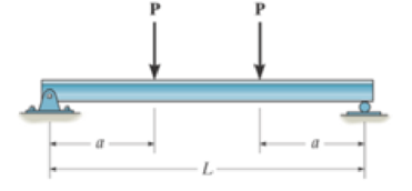
Prob. 7–46
Expert Solution & Answer
Want to see the full answer?
Check out a sample textbook solution
Students have asked these similar questions
THEMAGI
*7-48. Draw the shear and moment diagrams for the
cantilevered beam.
A
-5 ft-
800 lb-ft
B
Prob. 7-48
5 ft-
100 lb
C
Draw the shear and moment diagrams for the
beam. W= 30 kN/m M = 165 KN*
P= 25 KN
W
8 m
B
3 m
M
Determine where the maximum displacement of the following beam is happening
and what its value is. Finally, what would be the displacement in the middle of
the beam? Sketch first the shear force diagram and the bending moment
diagram.
I.
MB
-A
В-
Chapter 7 Solutions
PEARSON ETEXT ENGINEERING MECH & STATS
Ch. 7 - Determine the normal force, shear force, and...Ch. 7 - Determine the normal force, shear force, and...Ch. 7 - Determine the normal force, shear force, and...Ch. 7 - Determine the normal force, shear force, and...Ch. 7 - Determine the normal force, shear force, and...Ch. 7 - Determine the normal force, shear force, and...Ch. 7 - Determine the shear force and moment at points C...Ch. 7 - The pliers are used to grip the tube at B. If a...Ch. 7 - Determine the distance a as a fraction of the...Ch. 7 - The cable will fail when subjected to a tension of...
Ch. 7 - Determine the distance a between the bearings in...Ch. 7 - The cantilevered rack is used to support each end...Ch. 7 - Rod AB is fixed to a smooth collar D, which slides...Ch. 7 - Prob. 22PCh. 7 - Determine the normal force, shear force, and...Ch. 7 - The distributed loading W = W0 sin , measured per...Ch. 7 - Solve Prob. 7-39 for = 120. Probs. 739/40Ch. 7 - Determine the x, y, z components of force and...Ch. 7 - Determine the x, y, z components of internal...Ch. 7 - Determine the shear and moment as a function of x,...Ch. 7 - Determine the shear and moment as a function of x,...Ch. 7 - Determine the shear and moment as a function of x,...Ch. 7 - Determine the shear and moment as a function of x,...Ch. 7 - Determine the shear and moment as a function of x,...Ch. 7 - Determine the shear and moment as a function of x,...Ch. 7 - Draw the shear and moment diagrams for the shaft...Ch. 7 - Draw the shear and moment diagrams for the beam...Ch. 7 - Draw the shear and moment diagrams for the beam...Ch. 7 - Draw the shear and moment diagrams for the...Ch. 7 - Draw the shear and moment diagrams of the beam (a)...Ch. 7 - If L = 9 m, the beam will fail when the maximum...Ch. 7 - Draw the shear and moment diagrams for the beam....Ch. 7 - Draw the shear and moment diagrams for the beam....Ch. 7 - The shaft is supported by a smooth thrust bearing...Ch. 7 - Draw the shear and moment diagrams for the beam....Ch. 7 - Prob. 58PCh. 7 - Prob. 59PCh. 7 - The shaft is supported by a smooth thrust bearing...Ch. 7 - Draw the shear and moment diagrams for the beam....Ch. 7 - Prob. 65PCh. 7 - Draw the shear and moment diagrams for the beam....Ch. 7 - Draw the shear and moment diagrams for the beam....Ch. 7 - Draw the shear and moment diagrams for the beam....Ch. 7 - Draw the shear and moment diagrams for the beam....Ch. 7 - Draw the shear and moment diagrams for the beam....Ch. 7 - Draw the shear and moment diagrams for the beam....Ch. 7 - Draw the shear and moment diagrams for the beam....Ch. 7 - Draw the shear and moment diagrams for the beam....Ch. 7 - Draw the shear and moment diagrams for the beam....Ch. 7 - Draw the shear and moment diagrams for the beam....Ch. 7 - Draw the shear and moment diagrams for the beam....Ch. 7 - Draw the shear and moment diagrams for the beam....Ch. 7 - Draw the shear and moment diagrams for the beam....Ch. 7 - The cable supports the three loads shown....Ch. 7 - Prob. 95PCh. 7 - Determine the tension in each segment of the cable...Ch. 7 - Prob. 97PCh. 7 - The cable supports the loading shown. Determine...Ch. 7 - The cable supports the three loads shown....Ch. 7 - The cable supports the three loads shown....Ch. 7 - Determine the maximum uniform loading w, measured...Ch. 7 - The cable is subjected to a uniform loading of w =...Ch. 7 - If x = 2 ft and the crate weighs 300 lb, which...Ch. 7 - If yB = 1.5 ft. determine the largest weight of...Ch. 7 - The cable supports a girder which weighs 850...Ch. 7 - If the pipe has a mass per unit length of 1500...Ch. 7 - Prob. 110PCh. 7 - The cable will break when the maximum tension...Ch. 7 - Prob. 2RPCh. 7 - Prob. 3RPCh. 7 - Prob. 4RPCh. 7 - Draw the shear and moment diagrams for the beam....Ch. 7 - A chain is suspended between points at the same...
Knowledge Booster


Learn more about
Need a deep-dive on the concept behind this application? Look no further. Learn more about this topic, mechanical-engineering and related others by exploring similar questions and additional content below.Similar questions
- Draw the shear diagram for the beam. Set P = 800 lb, a = 5 ft, L = 12 ft. Draw the moment diagram for the beam. Set P = 800 lb, a = 5 ft, L = 12 ft.arrow_forward/The overhanging beam AE is subject to uniform normal loadings in the regions AB and DE, together with a couple acting at the midpoint C as shown in. plot the shear and moment diagram if Rp-3933 N. 200 N - m 4000 N/m 4000 N/m A E 1 m 1.5 m 1.5 m 1 m Rp Rgarrow_forward4. Draw the load and moment diagrams given the shear diagram as shown. Show all the values at different points of the beam. F10 m-10 m-t-10 m AV T 1500 N 334 N 834 Narrow_forward
- Question 3: The beam is subjected to the uniform distributed load shown. Draw the shear and moment diagrams for the beam. Take: A = C kN/m 2 B = 1.5 m C = kN /m B В m A m 1m Solution: Equation of Equilibrium: C(A+1) kN C kNlm 0.5(A+1) m Ax 4 AM Im Fec A meter (a) (b) 2MA = 0; Fec (3 /5)A – 0.5C(A +1)° = 0 F, = 0; A, + Fec (3/5)- C(A +1) = 0 kN A, = kN kN V, = M(KN.M) m X2 v3 M1 V2 kN vl V, = kN x2 x2 м, M3 M, = v2 (C) (d)arrow_forwardDetermine the equations of bending moment and shear force for 0arrow_forwarddraw the shear force moment diagram of the beam. 18 kN 6 kN 1m B Y M = 10 kN-m - 2 m- - 2 m - 2 marrow_forwardDraw the shear and moment diagram of the overhanging beam shown below. For this part, please show the necessary solutions using the long method, not the area moment method. Each correct line/curve with degrees equates to 1 pt. 4 kN/m В. 3 m 3 marrow_forwardIn each case, the beam is subjected to the loadings shown. Draw the free-body diagram of the beam, and sketch the general shape of the shear and moment diagrams. The loads and geometry are assumed to be known.arrow_forwardQuestion 3: The beam is subjected to the uniform distributed load shown. Draw the shear and moment diagrams for the beam. Take : A = C kN/m т 9 В - 6.75 m C = 9 kN/ m B B m A m 1 m Solution : Equation of Equilibrium: C KNIm C(A+1) kN 0.5(A+1) m Ax As, AM Im Fec Ay A meter (a) (b) EM, = 0; Fac(3/5)A-0.5C(A+1) =0 EF, = 0; A, +Fc(3/5)-C(A+1)=0 FBC kN Ay kN kN M(KN.M) m X2 v3 M1 V2 kN v1 kN x2 x2 M3 M3 v2 (C) (d) I| ||||arrow_forwardGiven the 12 m long Beam with Shear Diagram as shown below. Determine the following: +21 N + 2 N 3 m 6m The Moment at the Midspan of the Beam. The Maximum Moment in the Beam. - 23 Narrow_forwardDetermine the bending moment M in the beam at the point located 0.44 m to the right of point B. The ground reactions and shear-force diagram are shown.arrow_forwardGiven the 13 m long Beam with Shear Diagram as shown below. Determine the following: +18 N 2m 3m 1 The Moment at the Midspan of the Beam. The Maximum Moment in the Beam. - 30 Narrow_forwardarrow_back_iosSEE MORE QUESTIONSarrow_forward_ios
Recommended textbooks for you
 Elements Of ElectromagneticsMechanical EngineeringISBN:9780190698614Author:Sadiku, Matthew N. O.Publisher:Oxford University Press
 Mechanics of Materials (10th Edition)Mechanical EngineeringISBN:9780134319650Author:Russell C. HibbelerPublisher:PEARSON
 Thermodynamics: An Engineering ApproachMechanical EngineeringISBN:9781259822674Author:Yunus A. Cengel Dr., Michael A. BolesPublisher:McGraw-Hill Education
 Control Systems EngineeringMechanical EngineeringISBN:9781118170519Author:Norman S. NisePublisher:WILEY
 Mechanics of Materials (MindTap Course List)Mechanical EngineeringISBN:9781337093347Author:Barry J. Goodno, James M. GerePublisher:Cengage Learning
 Engineering Mechanics: StaticsMechanical EngineeringISBN:9781118807330Author:James L. Meriam, L. G. Kraige, J. N. BoltonPublisher:WILEY
Elements Of Electromagnetics
Mechanical Engineering
ISBN:9780190698614
Author:Sadiku, Matthew N. O.
Publisher:Oxford University Press
Mechanics of Materials (10th Edition)
Mechanical Engineering
ISBN:9780134319650
Author:Russell C. Hibbeler
Publisher:PEARSON
Thermodynamics: An Engineering Approach
Mechanical Engineering
ISBN:9781259822674
Author:Yunus A. Cengel Dr., Michael A. Boles
Publisher:McGraw-Hill Education
Control Systems Engineering
Mechanical Engineering
ISBN:9781118170519
Author:Norman S. Nise
Publisher:WILEY
Mechanics of Materials (MindTap Course List)
Mechanical Engineering
ISBN:9781337093347
Author:Barry J. Goodno, James M. Gere
Publisher:Cengage Learning
Engineering Mechanics: Statics
Mechanical Engineering
ISBN:9781118807330
Author:James L. Meriam, L. G. Kraige, J. N. Bolton
Publisher:WILEY
Mechanics of Materials Lecture: Beam Design; Author: UWMC Engineering;https://www.youtube.com/watch?v=-wVs5pvQPm4;License: Standard Youtube License