
Videos
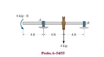
The tubular shaft is supported by a smooth thrust bearing al B and smooth journal bearing al A. If the material has an allowable bending stress of
Want to see the full answer?
Check out a sample textbook solution
Chapter 6 Solutions
Mechanics of Materials


- Determine the absolute maximum bending stress in the tubular shaft if di = 160 mm and do = 200 mmarrow_forwardThe copper shaft is subjected to the axial loads shown. Determine the displacement of end A with respect to end D if the diameters of each segment are dAB = 20mm, dBC = 25mm, and dCD = 12mm. Take Ecu = 126GPa.arrow_forwardThe shaft is subjected to the vertical and horizontal loadings of two pulleys D and E as shown. It is supported on two journal bearings at A and B which offer no resistance to axial loading. Furthermore, the coupling to the motor at C can be assumed not to offer any support to the shaft. Determine the required diameter d of the shaft if the allowable bending stress is sallow = 180 MPa.arrow_forward
- The electric motor exerts a torque of 800 N- m on the steel shaft ABCD when it is rotating at a constant speed. The angle of twist between A and D is limited to 1.50 degree. Use maximum shear = 60 MPa and modulus of rigidity = 77 GPa. Solve its torque for each shaft AB and BC. And determine the diameter of the Shaft based on strength. 300 N.m 500 N.m 0.4 m 0.6 m 0.3 marrow_forwardDetermine the smallest allowable diameter of the shaft which is subjected to the concentrated forces. The journal bearing at A and B only support vertical forces. The allowable bending stress is σallow= 160 MPa Bearing A only receives forces in the radial direction of the bearing. Bearing B is a steering bearing and also carries longitudinal loads on the shaft. F1= 10kN F2=23 kN L1=420 mm L2= 310mm L3=540mmarrow_forwardThe shaft consists of three concentric tubes, each made from the same material and having inner and outer radii as given below. Length of shaft is 2m. One end is fixed to the wall and to the other end a disc is attached. If a torque of T =800 N.m is applied at the disc end, determine the maximum shear stress in the shaft. 1. Inner tube: r; = 20mm, r, = 25 mm 2. Center tube: r; = 26 mm, r. = 30 mm 3. Outer tube: r = 32mm, r, = 38mmarrow_forward
- The axle of the freight train is subjected to loadings as shown below. The diameter of the axle is 137.5 mm. If it is supported by two journal bearings at C and D, determine the maximum bending stress. Include a FBD, SFD and BMD using either the section or graphical method. Draw a cross-section of the shaft and indicate the points of maximum tension and compression. A B 250 mm 100 kN 1500 mm- Answer 0= +98 MPa 250 mm 100 kNarrow_forwardtwo solid steel shafts of different diameters are joined together at point C. the diameter of the smaller shaft is 0.5 in, while the diameter of the larger shaft is 1 in. if the supports at both ends, A & B, are unyielding / rigid, and a counterclockwise torque of 500 ft lb at point D, determine the maximum shear stress in the shaft in ksi. The modulus of rigidity for steel is 10800 ksi.Show full solution pleasearrow_forwardAn A-36 steel strap having a thickness of 10 mm and a width of 20 mm is bent into a circular arc of radius r = 10 m. Determine the maximum bending stress in the strap.arrow_forward
- 1. The solid shaft is loaded (two point loads) and supported (fixed at left end) as shown. For the xyz directions shown, determine a) 手 B The normal stress at point B; The shear stress at point B; Show results on a differential volume element located at B. 4 in. 19 in. 4 in. 1.5 kips 12 kips 8 in. Section Properties of the shaft: A = 12.566 in.² II 12.566 in.4 (QB)V₂ = 0 in.³ (QB)V, = 5.333 in.³ J= 25.133 in.4arrow_forwardThe bar has a thickness of 0.5 in. and the allowable bending stress is sallow= 20 ksi. Determine the maximum moment M that can be applied.arrow_forwardTwo solid steel shafts of different diameters are joined together at point C. The diameter of the smaller shaft is 0.5 inch, while the diameter of the larger shaft is 1 inch. If the supports at both ends, A & B, are unyielding / rigid, and a counterclockwise torque of 500 ft lb is applied at point D, determine the maximum shear stress in the shaft in ksi. The modulus of rigidity for steel is 10800 ksi. 8 in 5 in 12 inarrow_forward
 Elements Of ElectromagneticsMechanical EngineeringISBN:9780190698614Author:Sadiku, Matthew N. O.Publisher:Oxford University Press
 Mechanics of Materials (10th Edition)Mechanical EngineeringISBN:9780134319650Author:Russell C. HibbelerPublisher:PEARSON
 Thermodynamics: An Engineering ApproachMechanical EngineeringISBN:9781259822674Author:Yunus A. Cengel Dr., Michael A. BolesPublisher:McGraw-Hill Education
 Control Systems EngineeringMechanical EngineeringISBN:9781118170519Author:Norman S. NisePublisher:WILEY
 Mechanics of Materials (MindTap Course List)Mechanical EngineeringISBN:9781337093347Author:Barry J. Goodno, James M. GerePublisher:Cengage Learning
 Engineering Mechanics: StaticsMechanical EngineeringISBN:9781118807330Author:James L. Meriam, L. G. Kraige, J. N. BoltonPublisher:WILEY