
Vector Mechanics for Engineers: Statics, 11th Edition
11th Edition
ISBN: 9780077687304
Author: Ferdinand P. Beer, E. Russell Johnston Jr., David Mazurek
Publisher: McGraw-Hill Education
expand_more
expand_more
format_list_bulleted
Concept explainers
Videos
Textbook Question
Chapter 6.3, Problem 6.97P
The cab and motor units of the front-end loader shown are connected by a vertical pin located 2 m behind the cab wheels. The distance from C to D is 1 m. The center of gravity of the 300-kN motor unit is located at Gm, while the centers of gravity of the 100-kN cab and 75-kN load are located, respectively, at GC and Gl. Knowing that the machine is at rest with its brakes released, determine (a) the reactions at each of the four wheels, (b) the forces exerted on the motor unit at C and D.
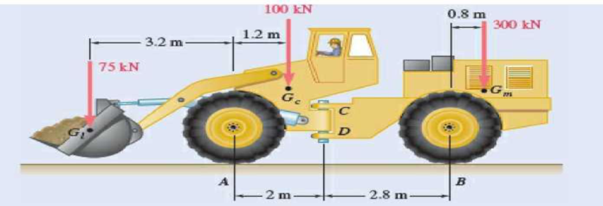
Fig. P6.97
Expert Solution & Answer
Want to see the full answer?
Check out a sample textbook solution
Students have asked these similar questions
The cab and motor units of the front-end loader shown are connected by a vertical pin located 2 m behind the cab wheels. The distance from C to D is 1 m. The center of gravity of the 300-kN motor unit is located at Gm , while the centers of gravity of the 100-kN cab and 75-kN load are located, respectively, at Gc and GI. . Knowing that the machine is at rest with its brakes released, determine (a) the reactions at each of the four wheels, (b) the forces exerted on the motor unit at C and D.
6.97 The cab and motor units of the front-end loader shown are connected
by a vertical pin located 2 m behind the cab wheels. The distance from
C to D is 1 m. The center of gravity of the 300-kN motor unit is located
at Gm, while the centers of gravity of the 100-kN cab and 75-kN load
are located, respectively, at Go and G₁. Knowing that the machine is at
rest with its brakes released, determine (a) the reactions at each of the
four wheels, (b) the forces exerted on the motor unit at C and D.
100 KN
0.8 m
G₁
75 kN
Fig. P6.97
3.2 m-
A
1.2 m
Gc
-2 m
$
D
2.8 m
B
300 KN
G
m
Solve Prob. 6.97 assuming that the 75-kN load has been removed.(Reference to Problem 6.97):The cab and motor units of the front-end loader shown are connected by a vertical pin located 2 m behind the cab wheels. The distance from C to D is 1 m. The center of gravity of the 300-kN motor unit is located at Gm , while the centers of gravity of the 100-kN cab and 75-kN load are located, respectively, at Gc and GI. . Knowing that the machine is at rest with its brakes released, determine (a) the reactions at each of the four wheels, (b) the forces exerted on the motor unit at C and D.
Chapter 6 Solutions
Vector Mechanics for Engineers: Statics, 11th Edition
Ch. 6.1 - 6.1 through 6.8 Using the method of joints,...Ch. 6.1 - Prob. 6.2PCh. 6.1 - Prob. 6.3PCh. 6.1 - 6.1 through 6.8 Using the method of joints,...Ch. 6.1 - 6.1 through 6.8 Using the method of joints,...Ch. 6.1 - Using the method of joints, determine the force in...Ch. 6.1 - 6.1 through 6.8 Using the method of joints,...Ch. 6.1 - Prob. 6.8PCh. 6.1 - 6.9 and 6.10 Determine the force in each member of...Ch. 6.1 - 6.9 and 6.10 Determine the force in each member of...
Ch. 6.1 - Determine the force in each member of the Gambrel...Ch. 6.1 - Determine the force in each member of the Howe...Ch. 6.1 - Using the method of joints, determine the force in...Ch. 6.1 - 6.14 Determine the force in each member of the...Ch. 6.1 - Determine the force in each member of the Warren...Ch. 6.1 - Solve Problem 6.15 assuming that the load applied...Ch. 6.1 - Determine the force in each member of the Pratt...Ch. 6.1 - The truss shown is one of several supporting an...Ch. 6.1 - Determine the force in each member of the Pratt...Ch. 6.1 - Solve Problem 6.19 assuming that the load applied...Ch. 6.1 - Determine the force in each of the members located...Ch. 6.1 - Determine the force in member DE and in each of...Ch. 6.1 - Determine the force in each of the members located...Ch. 6.1 - The portion of truss shown represents the upper...Ch. 6.1 - For the tower and loading of Prob. 6.24 and...Ch. 6.1 - Solve Problem 6.24 assuming that the cables...Ch. 6.1 - Determine the force in each member of the truss...Ch. 6.1 - Determine the force in each member of the truss...Ch. 6.1 - Prob. 6.29PCh. 6.1 - 6.30 Determine whether the trusses of Probs....Ch. 6.1 - 6.31 For the given loading. determine the...Ch. 6.1 - For the given loading, determine the zero-force...Ch. 6.1 - For the given loading, determine the zero-force...Ch. 6.1 - Determine the zero-force members in the truss of...Ch. 6.1 - The truss shown consists of six members and is...Ch. 6.1 - The truss shown consists of six members and is...Ch. 6.1 - The truss shown consists of six members and is...Ch. 6.1 - Prob. 6.38PCh. 6.1 - The truss shown consists of nine members and is...Ch. 6.1 - Solve Prob. 6.39 for P = 0 and Q = (900 N)k. 6.39...Ch. 6.1 - The truss shown consists of 18 members and is...Ch. 6.1 - The truss shown consists of 18 members and is...Ch. 6.2 - 6 .43 A Mansard roof truss is loaded as shown....Ch. 6.2 - Prob. 6.44PCh. 6.2 - Determine the force in members BD and CD of the...Ch. 6.2 - Determine the force in members DF and DG of the...Ch. 6.2 - 6.47 Determine the force in members CD and DF of...Ch. 6.2 - Prob. 6.48PCh. 6.2 - Determine the force in members CD and DF of the...Ch. 6.2 - Determine the force in members CE and EF of the...Ch. 6.2 - Determine the force in members DE and DF of the...Ch. 6.2 - Determine the force in members EG and EF of the...Ch. 6.2 - Determine the force in members DF and DE of the...Ch. 6.2 - Determine the force in members CD and CE of the...Ch. 6.2 - Prob. 6.55PCh. 6.2 - 6.56 A monosloped roof truss is loaded as shown....Ch. 6.2 - A Howe scissors roof truss is loaded as shown....Ch. 6.2 - A Howe scissors roof truss is loaded as shown....Ch. 6.2 - Determine the force in members AD, CD, and CE of...Ch. 6.2 - Determine the force in members DG, FG, and FH of...Ch. 6.2 - 6.61 Determine the force in members DC and FI of...Ch. 6.2 - Prob. 6.62PCh. 6.2 - Prob. 6.63PCh. 6.2 - Prob. 6.64PCh. 6.2 - The diagonal members in the center panels of the...Ch. 6.2 - The diagonal members in the center panels of the...Ch. 6.2 - The diagonal members in the center panels of the...Ch. 6.2 - Solve Prob. 6.67 assuming that the 9-kip load has...Ch. 6.2 - Classify each of the structures shown as...Ch. 6.2 - Classify each of the structures shown as...Ch. 6.2 - 6.70 through 6.74 classify as determinate or...Ch. 6.2 - 6.70 through 6.74 classify as determinate or...Ch. 6.2 - 6.70 through 6.74 classify as determinate or...Ch. 6.2 - 6.70 through 6.74 classify as determinate or...Ch. 6.3 - For the frame and loading shown, draw the...Ch. 6.3 - For the frame and loading shown, draw the...Ch. 6.3 - Draw the free-body diagram(s) needed to determine...Ch. 6.3 - Knowing that the pulley has a radius of 0.5 m,...Ch. 6.3 - 6.75 and 6.76 Determine the force in member BD and...Ch. 6.3 - 6.75 and 6.76 Determine the force in member BD and...Ch. 6.3 - For the frame and loading shown, determine the...Ch. 6.3 - Determine the components of all forces acting on...Ch. 6.3 - Prob. 6.79PCh. 6.3 - Prob. 6.80PCh. 6.3 - Determine the components of all forces acting on...Ch. 6.3 - Determine the components of all forces acting on...Ch. 6.3 - Determine the components of the reactions at A and...Ch. 6.3 - Determine the components of the reactions at D and...Ch. 6.3 - Determine the components of the reactions at A and...Ch. 6.3 - Determine the components of the reactions at A and...Ch. 6.3 - Prob. 6.87PCh. 6.3 - The 48-lb load can be moved along the line of...Ch. 6.3 - The 48-lb load is removed and a 288-lb in....Ch. 6.3 - (a) Show that, when a frame supports a pulley at...Ch. 6.3 - Knowing that each pulley has a radius of 250 mm,...Ch. 6.3 - Knowing that the pulley has a radius of 75 mm,...Ch. 6.3 - 6.93 A 3-ft-diameter pipe is supported every 16 ft...Ch. 6.3 - Prob. 6.94PCh. 6.3 - A trailer weighing 2400 lb is attached to a...Ch. 6.3 - In order to obtain a better weight distribution...Ch. 6.3 - The cab and motor units of the front-end loader...Ch. 6.3 - Solve Problem 6.97 assuming that the 75-kN load...Ch. 6.3 - Knowing that P = 90 lb and Q = 60 lb, determine...Ch. 6.3 - Knowing that P = 90 lb and Q = 60 lb, determine...Ch. 6.3 - For the frame and loading shown, determine the...Ch. 6.3 - For the frame and loading shown, determine the...Ch. 6.3 - 6.103 For the frame and loading shown, determine...Ch. 6.3 - Prob. 6.104PCh. 6.3 - For the frame and loading shown, determine the...Ch. 6.3 - Solve Prob. 6.105 assuming that the 6-kN load has...Ch. 6.3 - The axis of the three-hinge arch ABC is a parabola...Ch. 6.3 - The axis of the three-hinge arch ABC is a parabola...Ch. 6.3 - 6.109 and 6.110 Neglecting the effect of friction...Ch. 6.3 - and 6.110 Neglecting the effect of friction at the...Ch. 6.3 - 6.111, 6.112, and 6.113 Members ABC and CDE are...Ch. 6.3 - 6.111, 6.112, and 6.113 Members ABC and CDE are...Ch. 6.3 - 6.111, 6.112, and 6.113 Members ABC and CDE are...Ch. 6.3 - Prob. 6.114PCh. 6.3 - Solve Prob. 6.112 assuming that the force P is...Ch. 6.3 - Prob. 6.116PCh. 6.3 - Four beams, each with a length of 2a, are nailed...Ch. 6.3 - Four beams, each with a length of 3a, are held...Ch. 6.3 - 6.119 through 6.121 Each of the frames shown...Ch. 6.3 - 6.119 through 6.121 Each of the frames shown...Ch. 6.3 - 6.119 through 6.121 Each of the frames shown...Ch. 6.4 - An 84-lb force is applied to the toggle vise at C....Ch. 6.4 - For the system and loading shown, draw the...Ch. 6.4 - A small barrel weighing 60 lb is lifted by a pair...Ch. 6.4 - The position of member ABC is controlled by the...Ch. 6.4 - The shear shown is used to cut and trim...Ch. 6.4 - A 100-lb force directed vertically downward is...Ch. 6.4 - Prob. 6.124PCh. 6.4 - The control rod CE passes through a horizontal...Ch. 6.4 - Solve Prob. 6.125 when (a) = 0, (b) = 6. Fig....Ch. 6.4 - The press shown is used to emboss a small seal at...Ch. 6.4 - The press shown is used to emboss a small seal at...Ch. 6.4 - The pin at B is attached to member ABC and can...Ch. 6.4 - The pin at B is attached to member ABC and can...Ch. 6.4 - Arm ABC is connected by pins to a collar at B and...Ch. 6.4 - Arm ABC is connected by pins to a collar at B and...Ch. 6.4 - The Whitworth mechanism shown is used to produce a...Ch. 6.4 - Solve Prob. 6.133 when (a) = 60, (b) = 90. Fig....Ch. 6.4 - Prob. 6.135PCh. 6.4 - 6.135 and 6.136 Two rods are connected by a...Ch. 6.4 - 6.137 and 6.138 Rod CD is attached to the collar D...Ch. 6.4 - 6.137 and 6.138 Rod CD is attached to the collar D...Ch. 6.4 - Two hydraulic cylinders control the position of...Ch. 6.4 - Two hydraulic cylinders control the position of...Ch. 6.4 - Prob. 6.141PCh. 6.4 - Prob. 6.142PCh. 6.4 - 6.143 The tongs shown are used to apply a total...Ch. 6.4 - Prob. 6.144PCh. 6.4 - The pliers shown are used to grip a...Ch. 6.4 - Prob. 6.146PCh. 6.4 - In using the bolt cutter shown, a worker applies...Ch. 6.4 - Prob. 6.148PCh. 6.4 - and 6.150 Determine the force P that must be...Ch. 6.4 - and 6.150 Determine the force P that must be...Ch. 6.4 - Because the brace shown must remain in position...Ch. 6.4 - The specialized plumbing wrench shown is used in...Ch. 6.4 - Prob. 6.153PCh. 6.4 - Prob. 6.154PCh. 6.4 - The telescoping arm ABC is used to provide an...Ch. 6.4 - The telescoping arm ABC of Prob. 6.155 can be...Ch. 6.4 - The motion of the backhoe bucket shown is...Ch. 6.4 - Solve Prob. 6.157 assuming that the 2-kip force P...Ch. 6.4 - Prob. 6.159PCh. 6.4 - In the planetary gear system shown, the radius of...Ch. 6.4 - Two shafts AC and CF, which lie in the vertical xy...Ch. 6.4 - Two shafts AC and CF, which lie in the vertical xy...Ch. 6.4 - The large mechanical tongs shown are used to grab...Ch. 6 - Using the method of joints, determine the force in...Ch. 6 - Using the method of joints, determine the force in...Ch. 6 - A stadium roof truss is loaded as shown. Determine...Ch. 6 - A stadium roof truss is loaded as shown. Determine...Ch. 6 - Determine the components of all forces acting on...Ch. 6 - Determine the components of the reactions at A and...Ch. 6 - Knowing that the pulley has a radius of 50 mm,...Ch. 6 - For the frame and loading shown, determine the...Ch. 6 - For the frame and loading shown, determine the...Ch. 6 - Water pressure in the supply system exerts a...Ch. 6 - A couple M with a magnitude of 1.5 kNm is applied...Ch. 6 - The compound-lever pruning shears shown can be...
Knowledge Booster


Learn more about
Need a deep-dive on the concept behind this application? Look no further. Learn more about this topic, mechanical-engineering and related others by exploring similar questions and additional content below.Similar questions
- The telescoping arm ABC is used to provide an elevated platform for construction workers. The workers and the platform together have a mass of 200 kg and have a combined center of gravity located directly above C . For the position when 0= 20°, determine (a) the force exerted at B by the single hydraulic cylinder BD, (b) the force exerted on the supporting carriage at A.arrow_forwardQ.3) A luggage transport truck is used to raise and lower luggage from an aircraft. A piece of luggage weighing 450 lbs. is supported in the position shown with a center of gravity at point G. The raising and lowering mechanism are connected to the truck bed by a pin support at F and a roller support at H, and to the luggage platform by a pin support at C and a roller support at D. The hydraulic strut AB is pinned at either end and used to raise and lower the mechanism. Assume the weight of all members within the mechanism are negligible, that point C is vertically aligned with F, point D is vertically aligned with H, and that the strut AB is vertically 20maint oriented. (a) Determine the support reactions at F and H in the stationary position shown. (b) Determine the force in the hydraulic strut AB and state whether it is in tension or compression. 80000000 C 2.5 ft 0.5 ft 3 ft A B F G E H D 4 ft 4 ftarrow_forwardQ.1) Draw Free-Body diagrams of each of the three cylinders shown below. Each of the cylinders has a diameter of 12 inches and weight of 300 lb. Determine the forces exerted on each cylinder. B E 40° 40° C Farrow_forward
- [Chapter 4, Problem 4.41P The center of gravity of the 3000-lb car is at G. The car is parked on an incline with the parking brake engaged, which locks the rear wheels. Find (a) the normal forces (perpendicular to the incline) acting under the front and rear pairs of wheels; and (b) the friction force (parallel to the incline) under the rear pair of wheels. 2.2 ft A N₁ W cos(12) W -3 ft- - W sin (12) 6 ft f 44 N₂ x-axis y-axis 12°arrow_forward4. The 800 lb , 10 ftwide semicircular gate is to be opened as shown. What force P is needed if the center of gravity of the gate is 1 ft to the left of the hinge. 20 ft Gate of 5-ft radius H20 Hingearrow_forwardLet us model the illustrated crusher as a planar mechanism that is subjected to the pushing force P on the lower "L-shaped" handle, i.e. link CDE. Note that link CDE is one solid piece, pinned at D and E. Knowing that the orange horizontal member AB has a square peg at A that slides vertically in the slot on the blue frame, that the can is centered under the pin at B and that P = 60 N, 0 = 15°, 6 = 10°, a = 60 mm, b = 230 mm, c = 60 mm, and d = 25 mm, determine the force magnitude F in N exerted on the can from the mechanism. F = d A Probably the l loger in th N arls rg a B E b P Carrow_forward
- Two hydraulic cylinders control the position of the robotic arm ABC. In the position shown, the cylinders are parallel and both are in tension. Knowing that FAE = 600 N and FDG= 50 N, determine the forces P and Q applied at C to arm ABC.arrow_forwardTo loosen a frozen valve, a force F with a magnitude of 70 lb is applied to the handle of the valve. Knowing that 0= 25°, Mx = -61 lb·ft, and Mz = -43 lb·ft, determine? and d.arrow_forwardA luggage transport truck is used to raise and lower luggage from an aircraït. A piece of luggage weighing 450 lbs. is supported in the position shown with a center of gravity at point G. The raising and lowering mechanism are connected to the truck bed by a pin support at F and a roller support at H, and to the luggage platform by a pin support at C and a roller support at D. The hydraulic strut AB is pinned at either end and used to raise and lower the mechanism. Assume the weight of all members within the mechanism are negligible, that point C is vertically aligned with F, point D is vertically aligned with H, and that the strut AB is vertically oriented. (a) Determine the support reactions at and H in the stationary position shown. (b) Determine the force in the hydraulic strut AB and state whether it is in tension or compression. and 13 an C 2.5 ft 0.5 ft 3 ft A AB F G E H 13,7 4 ft 4 ftarrow_forward
- In order to unscrew the tapped faucet A , a plumber uses two pipe wrenches as shown. By exerting a 40-lb force on each wrench at a distance of 10 in. from the axis of the pipe and in a direction perpendicular to the pipe and to the wrench, he prevents the pipe from rotating, and thus he avoids loosening or further tightening the joint between the pipe and the tapped elbow C . Determine (a) the angle 0 that the wrench at A should form with the vertical if elbow C is not to rotate about the vertical, (b) the force-couple system at C equivalent to the two 40-lb forces when this condition is satisfied.arrow_forwardA freight wagon is at rest on a track at an angle of 25o to the vertical. The gross weight of the wagon and its load is 36kN and acts at a point 750 mm from the track, in the middle between the two axles. The wagon is held by a cable 600 mm from the track. Determine the traction on the cable and the reaction on each pair of wheels.arrow_forwardQ.1) Draw Free-Body diagrams of each of the three cylinders shown below. Each of the cylinders has a diameter of 15 inches and weight of 400 lb. Determine the forces exerted on each cylinder. A 40° B 40° D C G E Farrow_forward
arrow_back_ios
SEE MORE QUESTIONS
arrow_forward_ios
Recommended textbooks for you
 Elements Of ElectromagneticsMechanical EngineeringISBN:9780190698614Author:Sadiku, Matthew N. O.Publisher:Oxford University Press
 Mechanics of Materials (10th Edition)Mechanical EngineeringISBN:9780134319650Author:Russell C. HibbelerPublisher:PEARSON
 Thermodynamics: An Engineering ApproachMechanical EngineeringISBN:9781259822674Author:Yunus A. Cengel Dr., Michael A. BolesPublisher:McGraw-Hill Education
 Control Systems EngineeringMechanical EngineeringISBN:9781118170519Author:Norman S. NisePublisher:WILEY
 Mechanics of Materials (MindTap Course List)Mechanical EngineeringISBN:9781337093347Author:Barry J. Goodno, James M. GerePublisher:Cengage Learning
 Engineering Mechanics: StaticsMechanical EngineeringISBN:9781118807330Author:James L. Meriam, L. G. Kraige, J. N. BoltonPublisher:WILEY
Elements Of Electromagnetics
Mechanical Engineering
ISBN:9780190698614
Author:Sadiku, Matthew N. O.
Publisher:Oxford University Press
Mechanics of Materials (10th Edition)
Mechanical Engineering
ISBN:9780134319650
Author:Russell C. Hibbeler
Publisher:PEARSON
Thermodynamics: An Engineering Approach
Mechanical Engineering
ISBN:9781259822674
Author:Yunus A. Cengel Dr., Michael A. Boles
Publisher:McGraw-Hill Education
Control Systems Engineering
Mechanical Engineering
ISBN:9781118170519
Author:Norman S. Nise
Publisher:WILEY
Mechanics of Materials (MindTap Course List)
Mechanical Engineering
ISBN:9781337093347
Author:Barry J. Goodno, James M. Gere
Publisher:Cengage Learning
Engineering Mechanics: Statics
Mechanical Engineering
ISBN:9781118807330
Author:James L. Meriam, L. G. Kraige, J. N. Bolton
Publisher:WILEY
Dynamics - Lesson 1: Introduction and Constant Acceleration Equations; Author: Jeff Hanson;https://www.youtube.com/watch?v=7aMiZ3b0Ieg;License: Standard YouTube License, CC-BY