
Vector Mechanics for Engineers: Statics, 11th Edition
11th Edition
ISBN: 9780077687304
Author: Ferdinand P. Beer, E. Russell Johnston Jr., David Mazurek
Publisher: McGraw-Hill Education
expand_more
expand_more
format_list_bulleted
Videos
Textbook Question
Chapter 6.2, Problem 6.66P
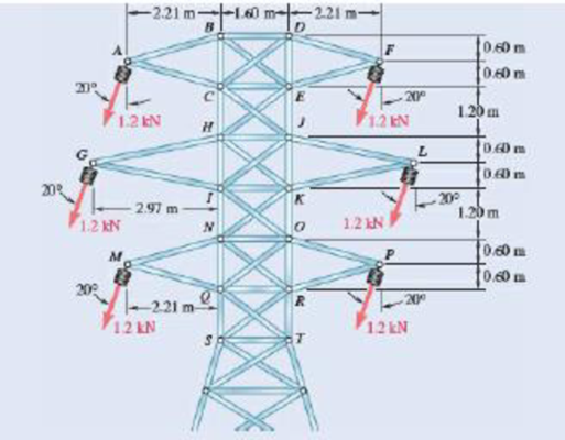
The diagonal members in the center panels of the power transmission line tower shown are very slender and can act only in tension; such members are known as counters. For given loading, determine (a) which of the two counters listed below is acting, (b) the force in that counter.
Counters IO and KN.
Expert Solution & Answer
Want to see the full answer?
Check out a sample textbook solution
Students have asked these similar questions
The cantilever truss shown is hinged at D and E. Find the forces in each
members.
5 kN
60°
60°
30°
E
3m
6m
5 kN
5 kN
A force P is applied to a bent rod that is supported by a roller and a pin and bracket. For each of the three cases shown, determine the internal forces at point J.
Determine the unknown forces by applying d’alemberts principle to a free body.
Chapter 6 Solutions
Vector Mechanics for Engineers: Statics, 11th Edition
Ch. 6.1 - 6.1 through 6.8 Using the method of joints,...Ch. 6.1 - Prob. 6.2PCh. 6.1 - Prob. 6.3PCh. 6.1 - 6.1 through 6.8 Using the method of joints,...Ch. 6.1 - 6.1 through 6.8 Using the method of joints,...Ch. 6.1 - Using the method of joints, determine the force in...Ch. 6.1 - 6.1 through 6.8 Using the method of joints,...Ch. 6.1 - Prob. 6.8PCh. 6.1 - 6.9 and 6.10 Determine the force in each member of...Ch. 6.1 - 6.9 and 6.10 Determine the force in each member of...
Ch. 6.1 - Determine the force in each member of the Gambrel...Ch. 6.1 - Determine the force in each member of the Howe...Ch. 6.1 - Using the method of joints, determine the force in...Ch. 6.1 - 6.14 Determine the force in each member of the...Ch. 6.1 - Determine the force in each member of the Warren...Ch. 6.1 - Solve Problem 6.15 assuming that the load applied...Ch. 6.1 - Determine the force in each member of the Pratt...Ch. 6.1 - The truss shown is one of several supporting an...Ch. 6.1 - Determine the force in each member of the Pratt...Ch. 6.1 - Solve Problem 6.19 assuming that the load applied...Ch. 6.1 - Determine the force in each of the members located...Ch. 6.1 - Determine the force in member DE and in each of...Ch. 6.1 - Determine the force in each of the members located...Ch. 6.1 - The portion of truss shown represents the upper...Ch. 6.1 - For the tower and loading of Prob. 6.24 and...Ch. 6.1 - Solve Problem 6.24 assuming that the cables...Ch. 6.1 - Determine the force in each member of the truss...Ch. 6.1 - Determine the force in each member of the truss...Ch. 6.1 - Prob. 6.29PCh. 6.1 - 6.30 Determine whether the trusses of Probs....Ch. 6.1 - 6.31 For the given loading. determine the...Ch. 6.1 - For the given loading, determine the zero-force...Ch. 6.1 - For the given loading, determine the zero-force...Ch. 6.1 - Determine the zero-force members in the truss of...Ch. 6.1 - The truss shown consists of six members and is...Ch. 6.1 - The truss shown consists of six members and is...Ch. 6.1 - The truss shown consists of six members and is...Ch. 6.1 - Prob. 6.38PCh. 6.1 - The truss shown consists of nine members and is...Ch. 6.1 - Solve Prob. 6.39 for P = 0 and Q = (900 N)k. 6.39...Ch. 6.1 - The truss shown consists of 18 members and is...Ch. 6.1 - The truss shown consists of 18 members and is...Ch. 6.2 - 6 .43 A Mansard roof truss is loaded as shown....Ch. 6.2 - Prob. 6.44PCh. 6.2 - Determine the force in members BD and CD of the...Ch. 6.2 - Determine the force in members DF and DG of the...Ch. 6.2 - 6.47 Determine the force in members CD and DF of...Ch. 6.2 - Prob. 6.48PCh. 6.2 - Determine the force in members CD and DF of the...Ch. 6.2 - Determine the force in members CE and EF of the...Ch. 6.2 - Determine the force in members DE and DF of the...Ch. 6.2 - Determine the force in members EG and EF of the...Ch. 6.2 - Determine the force in members DF and DE of the...Ch. 6.2 - Determine the force in members CD and CE of the...Ch. 6.2 - Prob. 6.55PCh. 6.2 - 6.56 A monosloped roof truss is loaded as shown....Ch. 6.2 - A Howe scissors roof truss is loaded as shown....Ch. 6.2 - A Howe scissors roof truss is loaded as shown....Ch. 6.2 - Determine the force in members AD, CD, and CE of...Ch. 6.2 - Determine the force in members DG, FG, and FH of...Ch. 6.2 - 6.61 Determine the force in members DC and FI of...Ch. 6.2 - Prob. 6.62PCh. 6.2 - Prob. 6.63PCh. 6.2 - Prob. 6.64PCh. 6.2 - The diagonal members in the center panels of the...Ch. 6.2 - The diagonal members in the center panels of the...Ch. 6.2 - The diagonal members in the center panels of the...Ch. 6.2 - Solve Prob. 6.67 assuming that the 9-kip load has...Ch. 6.2 - Classify each of the structures shown as...Ch. 6.2 - Classify each of the structures shown as...Ch. 6.2 - 6.70 through 6.74 classify as determinate or...Ch. 6.2 - 6.70 through 6.74 classify as determinate or...Ch. 6.2 - 6.70 through 6.74 classify as determinate or...Ch. 6.2 - 6.70 through 6.74 classify as determinate or...Ch. 6.3 - For the frame and loading shown, draw the...Ch. 6.3 - For the frame and loading shown, draw the...Ch. 6.3 - Draw the free-body diagram(s) needed to determine...Ch. 6.3 - Knowing that the pulley has a radius of 0.5 m,...Ch. 6.3 - 6.75 and 6.76 Determine the force in member BD and...Ch. 6.3 - 6.75 and 6.76 Determine the force in member BD and...Ch. 6.3 - For the frame and loading shown, determine the...Ch. 6.3 - Determine the components of all forces acting on...Ch. 6.3 - Prob. 6.79PCh. 6.3 - Prob. 6.80PCh. 6.3 - Determine the components of all forces acting on...Ch. 6.3 - Determine the components of all forces acting on...Ch. 6.3 - Determine the components of the reactions at A and...Ch. 6.3 - Determine the components of the reactions at D and...Ch. 6.3 - Determine the components of the reactions at A and...Ch. 6.3 - Determine the components of the reactions at A and...Ch. 6.3 - Prob. 6.87PCh. 6.3 - The 48-lb load can be moved along the line of...Ch. 6.3 - The 48-lb load is removed and a 288-lb in....Ch. 6.3 - (a) Show that, when a frame supports a pulley at...Ch. 6.3 - Knowing that each pulley has a radius of 250 mm,...Ch. 6.3 - Knowing that the pulley has a radius of 75 mm,...Ch. 6.3 - 6.93 A 3-ft-diameter pipe is supported every 16 ft...Ch. 6.3 - Prob. 6.94PCh. 6.3 - A trailer weighing 2400 lb is attached to a...Ch. 6.3 - In order to obtain a better weight distribution...Ch. 6.3 - The cab and motor units of the front-end loader...Ch. 6.3 - Solve Problem 6.97 assuming that the 75-kN load...Ch. 6.3 - Knowing that P = 90 lb and Q = 60 lb, determine...Ch. 6.3 - Knowing that P = 90 lb and Q = 60 lb, determine...Ch. 6.3 - For the frame and loading shown, determine the...Ch. 6.3 - For the frame and loading shown, determine the...Ch. 6.3 - 6.103 For the frame and loading shown, determine...Ch. 6.3 - Prob. 6.104PCh. 6.3 - For the frame and loading shown, determine the...Ch. 6.3 - Solve Prob. 6.105 assuming that the 6-kN load has...Ch. 6.3 - The axis of the three-hinge arch ABC is a parabola...Ch. 6.3 - The axis of the three-hinge arch ABC is a parabola...Ch. 6.3 - 6.109 and 6.110 Neglecting the effect of friction...Ch. 6.3 - and 6.110 Neglecting the effect of friction at the...Ch. 6.3 - 6.111, 6.112, and 6.113 Members ABC and CDE are...Ch. 6.3 - 6.111, 6.112, and 6.113 Members ABC and CDE are...Ch. 6.3 - 6.111, 6.112, and 6.113 Members ABC and CDE are...Ch. 6.3 - Prob. 6.114PCh. 6.3 - Solve Prob. 6.112 assuming that the force P is...Ch. 6.3 - Prob. 6.116PCh. 6.3 - Four beams, each with a length of 2a, are nailed...Ch. 6.3 - Four beams, each with a length of 3a, are held...Ch. 6.3 - 6.119 through 6.121 Each of the frames shown...Ch. 6.3 - 6.119 through 6.121 Each of the frames shown...Ch. 6.3 - 6.119 through 6.121 Each of the frames shown...Ch. 6.4 - An 84-lb force is applied to the toggle vise at C....Ch. 6.4 - For the system and loading shown, draw the...Ch. 6.4 - A small barrel weighing 60 lb is lifted by a pair...Ch. 6.4 - The position of member ABC is controlled by the...Ch. 6.4 - The shear shown is used to cut and trim...Ch. 6.4 - A 100-lb force directed vertically downward is...Ch. 6.4 - Prob. 6.124PCh. 6.4 - The control rod CE passes through a horizontal...Ch. 6.4 - Solve Prob. 6.125 when (a) = 0, (b) = 6. Fig....Ch. 6.4 - The press shown is used to emboss a small seal at...Ch. 6.4 - The press shown is used to emboss a small seal at...Ch. 6.4 - The pin at B is attached to member ABC and can...Ch. 6.4 - The pin at B is attached to member ABC and can...Ch. 6.4 - Arm ABC is connected by pins to a collar at B and...Ch. 6.4 - Arm ABC is connected by pins to a collar at B and...Ch. 6.4 - The Whitworth mechanism shown is used to produce a...Ch. 6.4 - Solve Prob. 6.133 when (a) = 60, (b) = 90. Fig....Ch. 6.4 - Prob. 6.135PCh. 6.4 - 6.135 and 6.136 Two rods are connected by a...Ch. 6.4 - 6.137 and 6.138 Rod CD is attached to the collar D...Ch. 6.4 - 6.137 and 6.138 Rod CD is attached to the collar D...Ch. 6.4 - Two hydraulic cylinders control the position of...Ch. 6.4 - Two hydraulic cylinders control the position of...Ch. 6.4 - Prob. 6.141PCh. 6.4 - Prob. 6.142PCh. 6.4 - 6.143 The tongs shown are used to apply a total...Ch. 6.4 - Prob. 6.144PCh. 6.4 - The pliers shown are used to grip a...Ch. 6.4 - Prob. 6.146PCh. 6.4 - In using the bolt cutter shown, a worker applies...Ch. 6.4 - Prob. 6.148PCh. 6.4 - and 6.150 Determine the force P that must be...Ch. 6.4 - and 6.150 Determine the force P that must be...Ch. 6.4 - Because the brace shown must remain in position...Ch. 6.4 - The specialized plumbing wrench shown is used in...Ch. 6.4 - Prob. 6.153PCh. 6.4 - Prob. 6.154PCh. 6.4 - The telescoping arm ABC is used to provide an...Ch. 6.4 - The telescoping arm ABC of Prob. 6.155 can be...Ch. 6.4 - The motion of the backhoe bucket shown is...Ch. 6.4 - Solve Prob. 6.157 assuming that the 2-kip force P...Ch. 6.4 - Prob. 6.159PCh. 6.4 - In the planetary gear system shown, the radius of...Ch. 6.4 - Two shafts AC and CF, which lie in the vertical xy...Ch. 6.4 - Two shafts AC and CF, which lie in the vertical xy...Ch. 6.4 - The large mechanical tongs shown are used to grab...Ch. 6 - Using the method of joints, determine the force in...Ch. 6 - Using the method of joints, determine the force in...Ch. 6 - A stadium roof truss is loaded as shown. Determine...Ch. 6 - A stadium roof truss is loaded as shown. Determine...Ch. 6 - Determine the components of all forces acting on...Ch. 6 - Determine the components of the reactions at A and...Ch. 6 - Knowing that the pulley has a radius of 50 mm,...Ch. 6 - For the frame and loading shown, determine the...Ch. 6 - For the frame and loading shown, determine the...Ch. 6 - Water pressure in the supply system exerts a...Ch. 6 - A couple M with a magnitude of 1.5 kNm is applied...Ch. 6 - The compound-lever pruning shears shown can be...
Knowledge Booster


Learn more about
Need a deep-dive on the concept behind this application? Look no further. Learn more about this topic, mechanical-engineering and related others by exploring similar questions and additional content below.Similar questions
- A snow load transfers the forces shown to the upper joints of a Pratt roof truss. Neglect any horizontal reactions at the supports solve for the forces in all members. Forces are positive if in tension, negative if in compression. 2.8 kN 2.8 kN 2.8 KN B HAL 2.2 m 2.2 m H 2.2 m G 2,2 m F 2.2 m 2.8 kN A D 2.8 KN Earrow_forwardUse the method of members to determine the true magnitude and direction of the forces in each of the members 1,2. Of the frame shown below in Fig 3.1arrow_forwardGroup A Ql- The uniform bar (AB) with end rollers has a weight of (294.3 N) and is supported by the horizontal and vertical surfaces and by the wire (AC). Calculate the tension (T) in the wire and the reactions against the rollers at A and B. o.6m 1.2m 1.6m Q2- Determine the magnitude and position of the resultant of the four parallel forces acting on the rocker arm of the figure. 50N 40N 20N 2- 3m Q3- Determine the reactions for the beam shown in the figure. 300 N Ho0 N l00 N/m om t 8m R2arrow_forward
- A transmission tower is held by three guy wires attached to a pin at A and anchored by bolts at B, C, and D . If the tension in wire AC is 590 lb, determine the vertical force P exerted by the tower on the pin at A.arrow_forwardA uniform horizontal strut weighs 425 N. One end of the strut is attached to a hinged support at the wall, and the other end of the strut is attached to a sign that weighs 235 N. The strut is also supported by a cable attached between the end of the strut and the wall. Assuming that the entire weight of the sign is attached at the very end of the strut, find the tension in the cable and the force at the hinge of the strut. Image Description T= Fhinge = N N 30° Restaurantarrow_forward2. A person's arm is used for ergonomic studies. If the distance of the AB, BC, and CD segments are 35.0 mm, 28.0 mm, and 19.0 mm, respectively, and the model is holding a small 1.5-lb load on the distal metacarpals of her hand . Determine the magnitude and direction of the moment of force with respect to a) to the shoulder joint, b) to the olecranon joint, c) to the carpal joint.arrow_forward
- 3. A 392-N force parallel to the plane is required to support a body on an inclined plane, of height 300 m and base 400 m. If the force exerted by the plane on the body is 780N, a. what is the weight of the body? b. what is the frictional force between the body and the plane?arrow_forward(A) Draw the components of the load in each member of the frame shown. Assume that BC and AC exert tension and CD exerts compression. Use the symbols Ax, Ay and Az for the x, y and z components respectively of force AC. Follow the same manner of representing the components of the forces in the other members, i.e., Bx, By, Bz and Dx, Dy and Dz accordingly. (B) Set up the equilibrium equation based on summation of moments about AB. Use the symbols indicated in (A). Take the counterclockwise moment as positive. (C) Set up the equilibrium equilibrium equation based on summation of moments about a vertical line passing through A (VA). Use the same symbols as in (A). Take the counterclockwise sense as positive. (D) Determine the load in member BC. Indicate if tension or compression. No need to convert units. express the answer in kips. y 24' 10 A 48' 20 kips Darrow_forwardGiven: P, = 200 lb, P, = 500 lb Find: The forces in each member of the truss. B P2 4 ft 3 ft 4 ftarrow_forward
- a. A plate is supported by 4 concurrent forces. If the resultant force on the plate is zero what will be the condition of the plate? b. A 600-lb force F1 and an 800-lb force F2 are applied to the plate through a smooth pin. i. Draw the free body diagram and ii. determine the magnitudes of forces FA and FB if the resultant R of the four forces is zero. Plz complete solution otherwise skip...arrow_forward)Use the method of MEMBERS to determine the true magnitude and direction of the forces in members1 and 2 of the frame shown below in Fig 3.2.arrow_forwardQuestion 4 (Type B): Determine the magnitudes of forces in members BF, DF, and DC using the method of section and identify whether they are in tension (T) or compression (C). A E B F₁ = 100 N 45° 2 m D F₂ = 50 N 2 m F 45°arrow_forward
arrow_back_ios
SEE MORE QUESTIONS
arrow_forward_ios
Recommended textbooks for you
 Elements Of ElectromagneticsMechanical EngineeringISBN:9780190698614Author:Sadiku, Matthew N. O.Publisher:Oxford University Press
 Mechanics of Materials (10th Edition)Mechanical EngineeringISBN:9780134319650Author:Russell C. HibbelerPublisher:PEARSON
 Thermodynamics: An Engineering ApproachMechanical EngineeringISBN:9781259822674Author:Yunus A. Cengel Dr., Michael A. BolesPublisher:McGraw-Hill Education
 Control Systems EngineeringMechanical EngineeringISBN:9781118170519Author:Norman S. NisePublisher:WILEY
 Mechanics of Materials (MindTap Course List)Mechanical EngineeringISBN:9781337093347Author:Barry J. Goodno, James M. GerePublisher:Cengage Learning
 Engineering Mechanics: StaticsMechanical EngineeringISBN:9781118807330Author:James L. Meriam, L. G. Kraige, J. N. BoltonPublisher:WILEY
Elements Of Electromagnetics
Mechanical Engineering
ISBN:9780190698614
Author:Sadiku, Matthew N. O.
Publisher:Oxford University Press
Mechanics of Materials (10th Edition)
Mechanical Engineering
ISBN:9780134319650
Author:Russell C. Hibbeler
Publisher:PEARSON
Thermodynamics: An Engineering Approach
Mechanical Engineering
ISBN:9781259822674
Author:Yunus A. Cengel Dr., Michael A. Boles
Publisher:McGraw-Hill Education
Control Systems Engineering
Mechanical Engineering
ISBN:9781118170519
Author:Norman S. Nise
Publisher:WILEY
Mechanics of Materials (MindTap Course List)
Mechanical Engineering
ISBN:9781337093347
Author:Barry J. Goodno, James M. Gere
Publisher:Cengage Learning
Engineering Mechanics: Statics
Mechanical Engineering
ISBN:9781118807330
Author:James L. Meriam, L. G. Kraige, J. N. Bolton
Publisher:WILEY
How to balance a see saw using moments example problem; Author: Engineer4Free;https://www.youtube.com/watch?v=d7tX37j-iHU;License: Standard Youtube License