
Vector Mechanics for Engineers: Statics, 11th Edition
11th Edition
ISBN: 9780077687304
Author: Ferdinand P. Beer, E. Russell Johnston Jr., David Mazurek
Publisher: McGraw-Hill Education
expand_more
expand_more
format_list_bulleted
Videos
Textbook Question
Chapter 6.2, Problem 6.73P
6.70 through 6.74 classify as determinate or indeterminate. (All members act both in tension and in compression.)
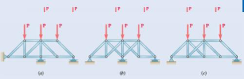
Fig. P6.73
Structure (a):
Rigid truss with r = 3, m = 14, n = 8,
so r + m = 17 > 2n = 16
so completely constrained but indeterminate
Structure (b): Simple truss (start with ABC and add joints alphabetically), with
r = 3, m = 13, n = 8, so r + m = 16 = 2n
so completely constrained and determinate
Structure (c):
Simple truss with r = 3, m = 13, n = 8, so r + m = 16 = 2n, hut horizontal reactions (Ax and Dx) are collinear, so cannot he resolved by any equilibrium equation.
Structure is improperly constrained.
Expert Solution & Answer
Want to see the full answer?
Check out a sample textbook solution
Students have asked these similar questions
Find the member forces in the truss shown below.
=
4 m
B
-
D
P = 50.0 KN
4 m
3 m
F(AB) - 23.6 kN (T). F(AD) 34.4 KN (T). F(CD)
O F(AB) 18.2 kN (T), F(AD) - 34.4 kN (T). F(CD) - 34.4 kN (T), F(CB)
C 1 m
14.4 kN (T), F(CB)
www.
F(AB) 18.2 kN (T), F(AD) - 34.4 kN (T), F(CD) - 34.4 kN (T). F(CB)
F(AB) 23.6 kN (T), F(AD)= 34.4 kN (T), F(CD) - 34.4 kN (T), F(CB)
57.1 kN (C), F(DB)
25.4 kN (T)
47.1 kN (C), F(DB)
16.67 kN (T)
47.1 kN (C). F(DB) = 25.4 kN (T)
47.1 kN (C), F(DB) 16.67 kN (T)
W
M
Q.1) For the following space truss where F1 = {300i + 400j -500k}, F2 = {600j}:
(a) Find the force in member CB, BE, and BA.
(b) State whether each member is in tension or compression.
NOTE: Joints A, B, E & F are located in the xy-plane. Similarly, joints C, D,
E & F are located in the xz-plane.
F
3'ft
F2
3 ft
-4 ft
Calculate the support reactions for the truss below. W = 4,4 kNh = 12,4 m
Chapter 6 Solutions
Vector Mechanics for Engineers: Statics, 11th Edition
Ch. 6.1 - 6.1 through 6.8 Using the method of joints,...Ch. 6.1 - Prob. 6.2PCh. 6.1 - Prob. 6.3PCh. 6.1 - 6.1 through 6.8 Using the method of joints,...Ch. 6.1 - 6.1 through 6.8 Using the method of joints,...Ch. 6.1 - Using the method of joints, determine the force in...Ch. 6.1 - 6.1 through 6.8 Using the method of joints,...Ch. 6.1 - Prob. 6.8PCh. 6.1 - 6.9 and 6.10 Determine the force in each member of...Ch. 6.1 - 6.9 and 6.10 Determine the force in each member of...
Ch. 6.1 - Determine the force in each member of the Gambrel...Ch. 6.1 - Determine the force in each member of the Howe...Ch. 6.1 - Using the method of joints, determine the force in...Ch. 6.1 - 6.14 Determine the force in each member of the...Ch. 6.1 - Determine the force in each member of the Warren...Ch. 6.1 - Solve Problem 6.15 assuming that the load applied...Ch. 6.1 - Determine the force in each member of the Pratt...Ch. 6.1 - The truss shown is one of several supporting an...Ch. 6.1 - Determine the force in each member of the Pratt...Ch. 6.1 - Solve Problem 6.19 assuming that the load applied...Ch. 6.1 - Determine the force in each of the members located...Ch. 6.1 - Determine the force in member DE and in each of...Ch. 6.1 - Determine the force in each of the members located...Ch. 6.1 - The portion of truss shown represents the upper...Ch. 6.1 - For the tower and loading of Prob. 6.24 and...Ch. 6.1 - Solve Problem 6.24 assuming that the cables...Ch. 6.1 - Determine the force in each member of the truss...Ch. 6.1 - Determine the force in each member of the truss...Ch. 6.1 - Prob. 6.29PCh. 6.1 - 6.30 Determine whether the trusses of Probs....Ch. 6.1 - 6.31 For the given loading. determine the...Ch. 6.1 - For the given loading, determine the zero-force...Ch. 6.1 - For the given loading, determine the zero-force...Ch. 6.1 - Determine the zero-force members in the truss of...Ch. 6.1 - The truss shown consists of six members and is...Ch. 6.1 - The truss shown consists of six members and is...Ch. 6.1 - The truss shown consists of six members and is...Ch. 6.1 - Prob. 6.38PCh. 6.1 - The truss shown consists of nine members and is...Ch. 6.1 - Solve Prob. 6.39 for P = 0 and Q = (900 N)k. 6.39...Ch. 6.1 - The truss shown consists of 18 members and is...Ch. 6.1 - The truss shown consists of 18 members and is...Ch. 6.2 - 6 .43 A Mansard roof truss is loaded as shown....Ch. 6.2 - Prob. 6.44PCh. 6.2 - Determine the force in members BD and CD of the...Ch. 6.2 - Determine the force in members DF and DG of the...Ch. 6.2 - 6.47 Determine the force in members CD and DF of...Ch. 6.2 - Prob. 6.48PCh. 6.2 - Determine the force in members CD and DF of the...Ch. 6.2 - Determine the force in members CE and EF of the...Ch. 6.2 - Determine the force in members DE and DF of the...Ch. 6.2 - Determine the force in members EG and EF of the...Ch. 6.2 - Determine the force in members DF and DE of the...Ch. 6.2 - Determine the force in members CD and CE of the...Ch. 6.2 - Prob. 6.55PCh. 6.2 - 6.56 A monosloped roof truss is loaded as shown....Ch. 6.2 - A Howe scissors roof truss is loaded as shown....Ch. 6.2 - A Howe scissors roof truss is loaded as shown....Ch. 6.2 - Determine the force in members AD, CD, and CE of...Ch. 6.2 - Determine the force in members DG, FG, and FH of...Ch. 6.2 - 6.61 Determine the force in members DC and FI of...Ch. 6.2 - Prob. 6.62PCh. 6.2 - Prob. 6.63PCh. 6.2 - Prob. 6.64PCh. 6.2 - The diagonal members in the center panels of the...Ch. 6.2 - The diagonal members in the center panels of the...Ch. 6.2 - The diagonal members in the center panels of the...Ch. 6.2 - Solve Prob. 6.67 assuming that the 9-kip load has...Ch. 6.2 - Classify each of the structures shown as...Ch. 6.2 - Classify each of the structures shown as...Ch. 6.2 - 6.70 through 6.74 classify as determinate or...Ch. 6.2 - 6.70 through 6.74 classify as determinate or...Ch. 6.2 - 6.70 through 6.74 classify as determinate or...Ch. 6.2 - 6.70 through 6.74 classify as determinate or...Ch. 6.3 - For the frame and loading shown, draw the...Ch. 6.3 - For the frame and loading shown, draw the...Ch. 6.3 - Draw the free-body diagram(s) needed to determine...Ch. 6.3 - Knowing that the pulley has a radius of 0.5 m,...Ch. 6.3 - 6.75 and 6.76 Determine the force in member BD and...Ch. 6.3 - 6.75 and 6.76 Determine the force in member BD and...Ch. 6.3 - For the frame and loading shown, determine the...Ch. 6.3 - Determine the components of all forces acting on...Ch. 6.3 - Prob. 6.79PCh. 6.3 - Prob. 6.80PCh. 6.3 - Determine the components of all forces acting on...Ch. 6.3 - Determine the components of all forces acting on...Ch. 6.3 - Determine the components of the reactions at A and...Ch. 6.3 - Determine the components of the reactions at D and...Ch. 6.3 - Determine the components of the reactions at A and...Ch. 6.3 - Determine the components of the reactions at A and...Ch. 6.3 - Prob. 6.87PCh. 6.3 - The 48-lb load can be moved along the line of...Ch. 6.3 - The 48-lb load is removed and a 288-lb in....Ch. 6.3 - (a) Show that, when a frame supports a pulley at...Ch. 6.3 - Knowing that each pulley has a radius of 250 mm,...Ch. 6.3 - Knowing that the pulley has a radius of 75 mm,...Ch. 6.3 - 6.93 A 3-ft-diameter pipe is supported every 16 ft...Ch. 6.3 - Prob. 6.94PCh. 6.3 - A trailer weighing 2400 lb is attached to a...Ch. 6.3 - In order to obtain a better weight distribution...Ch. 6.3 - The cab and motor units of the front-end loader...Ch. 6.3 - Solve Problem 6.97 assuming that the 75-kN load...Ch. 6.3 - Knowing that P = 90 lb and Q = 60 lb, determine...Ch. 6.3 - Knowing that P = 90 lb and Q = 60 lb, determine...Ch. 6.3 - For the frame and loading shown, determine the...Ch. 6.3 - For the frame and loading shown, determine the...Ch. 6.3 - 6.103 For the frame and loading shown, determine...Ch. 6.3 - Prob. 6.104PCh. 6.3 - For the frame and loading shown, determine the...Ch. 6.3 - Solve Prob. 6.105 assuming that the 6-kN load has...Ch. 6.3 - The axis of the three-hinge arch ABC is a parabola...Ch. 6.3 - The axis of the three-hinge arch ABC is a parabola...Ch. 6.3 - 6.109 and 6.110 Neglecting the effect of friction...Ch. 6.3 - and 6.110 Neglecting the effect of friction at the...Ch. 6.3 - 6.111, 6.112, and 6.113 Members ABC and CDE are...Ch. 6.3 - 6.111, 6.112, and 6.113 Members ABC and CDE are...Ch. 6.3 - 6.111, 6.112, and 6.113 Members ABC and CDE are...Ch. 6.3 - Prob. 6.114PCh. 6.3 - Solve Prob. 6.112 assuming that the force P is...Ch. 6.3 - Prob. 6.116PCh. 6.3 - Four beams, each with a length of 2a, are nailed...Ch. 6.3 - Four beams, each with a length of 3a, are held...Ch. 6.3 - 6.119 through 6.121 Each of the frames shown...Ch. 6.3 - 6.119 through 6.121 Each of the frames shown...Ch. 6.3 - 6.119 through 6.121 Each of the frames shown...Ch. 6.4 - An 84-lb force is applied to the toggle vise at C....Ch. 6.4 - For the system and loading shown, draw the...Ch. 6.4 - A small barrel weighing 60 lb is lifted by a pair...Ch. 6.4 - The position of member ABC is controlled by the...Ch. 6.4 - The shear shown is used to cut and trim...Ch. 6.4 - A 100-lb force directed vertically downward is...Ch. 6.4 - Prob. 6.124PCh. 6.4 - The control rod CE passes through a horizontal...Ch. 6.4 - Solve Prob. 6.125 when (a) = 0, (b) = 6. Fig....Ch. 6.4 - The press shown is used to emboss a small seal at...Ch. 6.4 - The press shown is used to emboss a small seal at...Ch. 6.4 - The pin at B is attached to member ABC and can...Ch. 6.4 - The pin at B is attached to member ABC and can...Ch. 6.4 - Arm ABC is connected by pins to a collar at B and...Ch. 6.4 - Arm ABC is connected by pins to a collar at B and...Ch. 6.4 - The Whitworth mechanism shown is used to produce a...Ch. 6.4 - Solve Prob. 6.133 when (a) = 60, (b) = 90. Fig....Ch. 6.4 - Prob. 6.135PCh. 6.4 - 6.135 and 6.136 Two rods are connected by a...Ch. 6.4 - 6.137 and 6.138 Rod CD is attached to the collar D...Ch. 6.4 - 6.137 and 6.138 Rod CD is attached to the collar D...Ch. 6.4 - Two hydraulic cylinders control the position of...Ch. 6.4 - Two hydraulic cylinders control the position of...Ch. 6.4 - Prob. 6.141PCh. 6.4 - Prob. 6.142PCh. 6.4 - 6.143 The tongs shown are used to apply a total...Ch. 6.4 - Prob. 6.144PCh. 6.4 - The pliers shown are used to grip a...Ch. 6.4 - Prob. 6.146PCh. 6.4 - In using the bolt cutter shown, a worker applies...Ch. 6.4 - Prob. 6.148PCh. 6.4 - and 6.150 Determine the force P that must be...Ch. 6.4 - and 6.150 Determine the force P that must be...Ch. 6.4 - Because the brace shown must remain in position...Ch. 6.4 - The specialized plumbing wrench shown is used in...Ch. 6.4 - Prob. 6.153PCh. 6.4 - Prob. 6.154PCh. 6.4 - The telescoping arm ABC is used to provide an...Ch. 6.4 - The telescoping arm ABC of Prob. 6.155 can be...Ch. 6.4 - The motion of the backhoe bucket shown is...Ch. 6.4 - Solve Prob. 6.157 assuming that the 2-kip force P...Ch. 6.4 - Prob. 6.159PCh. 6.4 - In the planetary gear system shown, the radius of...Ch. 6.4 - Two shafts AC and CF, which lie in the vertical xy...Ch. 6.4 - Two shafts AC and CF, which lie in the vertical xy...Ch. 6.4 - The large mechanical tongs shown are used to grab...Ch. 6 - Using the method of joints, determine the force in...Ch. 6 - Using the method of joints, determine the force in...Ch. 6 - A stadium roof truss is loaded as shown. Determine...Ch. 6 - A stadium roof truss is loaded as shown. Determine...Ch. 6 - Determine the components of all forces acting on...Ch. 6 - Determine the components of the reactions at A and...Ch. 6 - Knowing that the pulley has a radius of 50 mm,...Ch. 6 - For the frame and loading shown, determine the...Ch. 6 - For the frame and loading shown, determine the...Ch. 6 - Water pressure in the supply system exerts a...Ch. 6 - A couple M with a magnitude of 1.5 kNm is applied...Ch. 6 - The compound-lever pruning shears shown can be...
Knowledge Booster


Learn more about
Need a deep-dive on the concept behind this application? Look no further. Learn more about this topic, mechanical-engineering and related others by exploring similar questions and additional content below.Similar questions
- a) What is a truss? Explain shortly in your own words, and illustrate with one example. b) For the truss in the figure below, determine the zero-force members and give a short explanation to support your answer. B C D A H -1.5 m- G F -1.5 m 1.5 m-1.5 m-- 2 m 2 m Earrow_forwardActivity 1. For the truss shown in the figure, determine the forces acting on members AB, AC,BC,CE by method of joints.[Ans. AB=247.88KN(C), BC=50KN(T), CE=AC=206.25KN(T)] 100 N 50N 50 N 2m H 1.5m C 1.5m E 1.5m G 50N Activity 2. Solve for the force acting on members AB, AC and BC of the Warren Truss shown using method of joint. [Ans. AB=672KN(T), AC=300KN(C), BC=672KN(C)] 400 KN 300 KN D+ 6m 6m 6m 6m 600KN 200 KNarrow_forward5.3.4 Zero Force Members Figure H 800 N ALA F E MA 3m D -3 m 30% G B -3 m 20 1 of 2 ( 3m Figure B 2m 2 m C T 2 m < 2 of 2 D 4m 500 N 700 N Part A Identify the zero-force members in the truss shown in (Figure 1). Check all that apply. CD D BC D CE ⒸAB DE GH EF ооооооооооооо BG □ CF AG OBF FG ⒸAH Part B Identify the zero-force members in the truss shown in (Figure 2). Check all that apply. OBC FG D CF AG BG OCD DE ⒸAB D CG EF ODF оооооооооооarrow_forward
- A new art exhibit featuring mobile works is going up in the Norwalk, CA area. One art work is shown in the figure below. A 105 N uniform beam is pinned to the ground by a pivot. The beam is supported by a cable (attached 3/5 from the bottom of the beam) to allow for each of the shoes to hang freely. Each individual shoe has a weight of 7.5 N. 10 WALL FLOR (a) ( If one shoe is attached 1/7 of the way up the beam and another shoe is attached 5/8 of the way up the beam, with e, = 70.1° and e, 30.1°, what is the tension in the cable, in newtons? %3! %3D (b) What is the x-component of the force, in newtons, that the pivot exerts on the bottom of the beam? (c) O What is the y-component of the force, in newtons, that the pivot exerts on the bottom of the beam?arrow_forwardActivity 1. For the truss shown in the figure, determine the forces acting on members AB, AC,BC,CE by method of joints.[Ans. AB=247.88KN(C), BC=50KN(T), CE=AC=206.25KN(T)] 100 N D. 50N 50 N B. F 2m 1.5m |C 1.5m E 1.5m G 50Narrow_forward3) Calculate the internal forces in members DF, CE, and BD of the given truss shown in the figure below. Use the Method of Sections. G0ON GOON GOON GOON G0ON 1,5m 600 N B. 600 N A 6 at 1-20m = 7.20marrow_forward
- 5. Analyze the following trusses using the finite element method if E = 200GPA and area of cross section A = 2cm? for all members. 1m 1m 1m 1m 1.5m 1m P=50 kN P1=30 kN P2=65 kN (a) (b) Fig. P3.3arrow_forwardA simply supported span (middle span) of 6-m length with double cantilever of 1.5 m at each end is loaded as shown below. There is a concentrated moment of 6 kN-m acting at the tip of the left cantilever and a point load of 3 kN acting at the tip of the right cantilever. A concentrated force P = 10 kN is acting at the mid-point of the middle span. In addition, there are two partial uniform load of 5 kN/m acting on the middle span as shown below. The middle span has an I-section, of which the value of the moment of inertia I is given. The dimensions of the two flanges and the vertical web are also given. The right cantilever has a T-section. The dimensions of the top flange and the web are given. a).Calculate the maximum bending stress of the middle span and plot the bending stress distribution. The middle span is an I-section and the value of moment of inertia I is given as shown above b.) Calculate the maximum shear stress of the middle span and the shear stress at the interface…arrow_forwardA new art exhibit featuring mobile works is going up in the Holland, MI, area. One piece is shown in the figure. The 155-N uniform beam is pinned to the ground by a pivot. The beam is supported by a cable (attached to the center of the beam) to allow for each of the shoes to hang freely. Each individual shoe has a weight of 9.5-N. If one shoe is attached two-fifths of the way up the beam and another shoe is attached and three-fifths of the way up the beam, with θc = 16.5° and θb = 33.6° as shown in the figure, what is the tension in the cable, in newtons? What is the x-component of the force, in newtons, that the pivot exerts on the bottom of the beam? Use the coordinate system specified in the figure. What is the y-component of the force, in newtons, that the hinge exerts on the bottom of the beam? Use the coordinate system specified in the figure.arrow_forward
- PROBLEM NO. 2 A 12kN AND 50KN WEIGHTS ARE ATTACTHED TO THE CANTILEVER BEAM IN THE FIGURE BELOW CALCULATE THE TENSION OF THE CABLE IF THE PULLEY IS FRICTIONLESS, CALCULATE THE REACTION AT POINT A. 3. B 1.5 0.5 0.5 14 kN) 50 kNarrow_forward00 %24 Week4 Frames1 21-22-1 (1).pdf File C/Users/callu/Downloads/Week4 Frames1 21-22-1%20(1).pdf T Add text Draw E Highlight 2 Erase (D Page view IA Read aloud 5. Determine the support forces and force in each member of the truss in Fig. Q5 and state if the members are in tension or compression. 3 kN 1.5 m o0E = 0 B. 2 m 2 m 4 kN Fig. Q5 a) Draw FBD of truss ABCD and determine support forces at A and C. b) Draw FBD of pin at C. Determine unknown member forces. c) Draw FBD of pin at B. Determine unknown member forces. d) Draw FBD of pin at A. Determine unknown member force. [A,=1.2kN, A,=0.88KN, C,=1.8kN, C,=3.13KN, FBC= 2.37(T), FCD= 5.21(C), FAR 2.37(T), Fan= 4.0(T), FAD= 1.47(C)] %3D 14:56 12°C Raining now 31/10/2021 6. 五 O e A DO BANG &OL 12 61 delete home 144 pua I14 dn pd num 2. + backspace lock * 4. 5. 3. R { %#3 home 7. 4. prt scarrow_forwardL/2 L/2 L/4 F A cantilever beam of length L=3 m with a rigid extended rod of length L/4 welded at mid-span is loaded as shown, where F=5.15 kN, and 0=60 deg. (a) Draw the axial force diagram of the beam, and select the maximum magnitude of axial force value from the options below. (20% weightage) (b) Draw the shear force diagram of the beam, and select the shear force value with proper sign at the built-in (wall) end of the beam from the options below. (20% weightage) (c) Draw the bending diagram of the beam, and select the maximum magnitude of bending moment from the options below. (60% weightage) O Maximum axial force = 2.23 kN O Maximum bending moment value = 9.66 kNm O Shear force at built-in end = -3.22 kN O Maximum bending moment value = 15.45 kNm O Maximum axial force = 4.46 kN O Shear force at built-in end = -1.93 kN O Maximum axial force = 0.00 kN O Shear force at built-in end = -2.58 kN O Maximum bending moment value = 19.31 kNm O Maximum axial force = 2.58 kN O Maximum…arrow_forward
arrow_back_ios
SEE MORE QUESTIONS
arrow_forward_ios
Recommended textbooks for you
 Elements Of ElectromagneticsMechanical EngineeringISBN:9780190698614Author:Sadiku, Matthew N. O.Publisher:Oxford University Press
 Mechanics of Materials (10th Edition)Mechanical EngineeringISBN:9780134319650Author:Russell C. HibbelerPublisher:PEARSON
 Thermodynamics: An Engineering ApproachMechanical EngineeringISBN:9781259822674Author:Yunus A. Cengel Dr., Michael A. BolesPublisher:McGraw-Hill Education
 Control Systems EngineeringMechanical EngineeringISBN:9781118170519Author:Norman S. NisePublisher:WILEY
 Mechanics of Materials (MindTap Course List)Mechanical EngineeringISBN:9781337093347Author:Barry J. Goodno, James M. GerePublisher:Cengage Learning
 Engineering Mechanics: StaticsMechanical EngineeringISBN:9781118807330Author:James L. Meriam, L. G. Kraige, J. N. BoltonPublisher:WILEY
Elements Of Electromagnetics
Mechanical Engineering
ISBN:9780190698614
Author:Sadiku, Matthew N. O.
Publisher:Oxford University Press
Mechanics of Materials (10th Edition)
Mechanical Engineering
ISBN:9780134319650
Author:Russell C. Hibbeler
Publisher:PEARSON
Thermodynamics: An Engineering Approach
Mechanical Engineering
ISBN:9781259822674
Author:Yunus A. Cengel Dr., Michael A. Boles
Publisher:McGraw-Hill Education
Control Systems Engineering
Mechanical Engineering
ISBN:9781118170519
Author:Norman S. Nise
Publisher:WILEY
Mechanics of Materials (MindTap Course List)
Mechanical Engineering
ISBN:9781337093347
Author:Barry J. Goodno, James M. Gere
Publisher:Cengage Learning
Engineering Mechanics: Statics
Mechanical Engineering
ISBN:9781118807330
Author:James L. Meriam, L. G. Kraige, J. N. Bolton
Publisher:WILEY
Differences between Temporary Joining and Permanent Joining.; Author: Academic Gain Tutorials;https://www.youtube.com/watch?v=PTr8QZhgXyg;License: Standard Youtube License