(a)
The components of the forces exerted on member BCDF at C and D.
(a)
Answer to Problem 6.104P
The x component of force at D,
Explanation of Solution
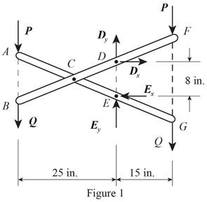
Figure 1 is the free body diagram of the entire frame of the system.

Write the equation to find the sum of the moments about point E.
Here,
Write the equation to find the sum of x components of force.
Here,
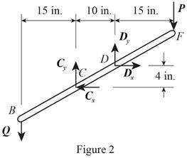
Consider the member BCDF of the system.
Figure 2 shown below is the free body diagram of member BCDF.

Write the equation to find the sum of x component of force.
Here,
Write the equation to find the sum of moments at D.
Here,
Write the equation to find the sum of y components of force.
Here,
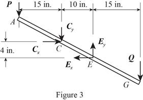
Consider the free body diagram of member ACEG. The free body diagram of ACEG is given in figure 3.

Write the equation to find the sum of y component of force.
Here,
Conclusion:
Solve equation (I) to get the value of
Substitute
Solve equation (III) to get the value of
Substitute
Substitute
 Substitute
Substitute
Substitute
Therefore, The x component of force at D,
(b)
The component of force on member ACEG at E.
(b)
Answer to Problem 6.104P
The x component of force at E,
Explanation of Solution
Rewrite equation (II) to find the x component of force at E.
Here,
Rewrite equation (VI) to get the y component of force at E.
Here,
Conclusion:
Substitute
Substitute
Substitute
Substitute

Therefore, The x component of force at E,
Want to see more full solutions like this?
Chapter 6 Solutions
Vector Mechanics for Engineers: Statics
- 14.14. A three-stage evaporator is fed with 1.25 kg/s of a liquor which is concentrated from 10 to 40 per cent solids by mass. The heat transfer coefficients may be taken as 3.1, 2.5 and 1.7 kW/m² K, respectively, in each effect. Calculate the steam flow at 170 kN/m² and the temperature distribution in the three effects, if: (a) the feed is at 294 K, and (b) the feed is at 355 K. Forward feed is used in each case and the values of U are the same for the two systems. The boiling point in the third effect is 325 K and the liquor has no boiling point rise. Oarrow_forwardForm of the second question 3 Question 2: 500 In the figure shown, gear 2 rotates at 1000rpm. It transmits a power of 5kw to gear 4 via gear Loose 3 idler all gears spur, angle Gear pressure =200, and inclusion = 5m. Draw Analyze the forces on gear 3 and then find the reactions on Column 6, knowing the number of teeth N₂ = 12, N3 = 60, N₁ = 40arrow_forwardExample (7): Determine the heating surface area required for the production of 2.5kg/s of 50wt% NaOH solution from 15 wt% NaOH feed solution which entering at 100 oC to a single effect evaporator. The steam is available as saturated at 451.5K and the boiling point rise (boiling point evaluation) of 50wt% solution is 35K. the overall heat transfer coefficient is 2000 w/m²K. The pressure in the vapor space of the evaporator at atmospheric pressure. The solution has a specific heat of 4.18kJ/ kg.K. The enthalpy of vaporization under these condition is 2257kJ/kg Example (6): 5:48 م An evaporator is concentrating F kg/h at 311K of a 20wt% solution of NaOH to 50wt %. The saturated steam used for heating is at 399.3K. The pressure in the vapor space of the evaporator is 13.3 KPa abs. The 5:48 Oarrow_forward
- Design a speed warning system that receives on two lines, an indication of the speed limit on the highway. There are three possible values 45, 55, or 65 MPH. It receives from the automobile, on two other lines, an indication of the speed of the vehicle. There are four possible values under 45, between 46 and 55, between 56 and 65, and over 65 MPH. It produces two outputs. The first, F, indicates whether the car is going above the speed limit. The second, G, indicates that the car is driving at a "dangerous speed" _ defined as either over 65 MPH or more than 10 MPH above the speed limit. The inputs are coded as follows: Speed limit A B Speed C D 45 0 0 65 1 1 a) Complete the Truth table for the speed warning system Inputs Outputs A B C D F G b) Write the Minterm expressions for the Output Functions. c) Minimize the output functions d) Implement the logic e) Using LabView, verify the Correctness of the Speed Warning System.arrow_forwardEx. The cantilever beam shown us, made ofrem steel with = 552 MPa is , ut subjected to fully reversed load. Neglect shear stress effect, estimate wheather the beam is safe or not safe at N= lo cycles 9 The beam is machined surface and the operating temp. is 100C. A F 200 a=0 N -200 N 1 L= 10cm D time 764 Yze.25 Gm L D= 1.3 cm d = 1 cm b= 1 cm -momend diagram AA -FL at the root of the cantilever, the bending moment is max. factor Ex. Repeat Ex. in page (24), with fluctuating load as shown below. By = 46242,041 = 552 MPa. Find the safety (NF) using Modified -Goodman, Gerber, and soderberg criterias F(N). ....400 timearrow_forwardExample The bar Shown Is. subsected to combined loadings as follows: P = = 20.KN F = 0 to 2 KN T= 0-5 KN.m The bar material has Se=400 mpa and out = 1379 MPa, Yiu= 1000 mpa Find the factor of safety, neglect the transverse Shear- Sol I load analysis ар F T Par = 20 KN (axial load- Pmim = -20 KN fully reversed dynamic) Emark 2km = Fmim = 0 N (bending loading -dynamic) Repeated D=20mm d=15 mm r=5mm L= =250mmarrow_forward
- PL 120.8 Paie An extrusion operation produces the cross section shown in the figure below from a billet whose diameter = 100 mm The flow curve for the billet is define by σ = 160 €0.18. Determine extrusion force when (300,200 and 100) mm length remaining in the container. and blarrow_forwardEXAM/3 Q/In the figure below the clamping force on the pipe is (331.7 lb), knowing that a single threaded screw Acme with major diameter (1 in) is used with coefficient of sliding friction (0.2135) and booth screw and nut are made from 1030 - hot rolled Carbon Steel. If the collar has a rolling friction of 0.02 and the mean collar diameter is 1.75 in. Determine: 1- The tightening and loosening torques. Is it self-locking? 2- Thread screw and nut induced stresses. w*7.3+² + Fx (7.3+1+6+43)) Fy (3 10 3.3 in Fx 421 3.3 (sin( 'in 3 in ?) 32° hinge "Sin (12")arrow_forwardQ1: At a constant velocity of 20 m/s, air passes across a flat plate with ambient pressure and temperature of 20 kPa and 20°C. At a distance of 7.5 cm from the leading edge, the plate is heated to a constant temperature of 75°C. How much heat is transferred overall from the leading edge to a location 35 cm from the leading edge? Tw Q2: The critical Reynolds number for flow over a flat plate in a particular application is 10°. This critical Reynolds number and an isothermal plate temperature of 400 K are encountered by air flowing across it at 1 atm, 300 K, and 10 m/s. At the end of the plate, the Reynolds number is 5 x 10⁶. What will average heat transfer coefficient be for this system? What is the length of the plate? What is the plate's loss of heat? Re 21 Wat Q3: At 50 kPa and 300 K, air moves at an average velocity of 6 m/s across a 20-cm- Thoo P square plate. To provide a steady flow of heat, an electrical heater is mounted within the plate. If the plate temperature is limited to…arrow_forward
- Quiz/Find the state of stresses and principal stresses at point (A)and point (B) for the circular cantilever rod of a diameter (5 cm) shown in figure bellow. Knowing that the rod is subjected to a force (F= 12 kN), axial force (P=2 kN) and to a torque (T= 488π N.m). P=2 kN T L= 300 mm Samsung Quad Camera galaxy A9arrow_forwardهنا زيد علي عبد المحسن Quiz/ If the weld size equal to (0.9 cm) find the max allowable shear stress (Tmax) for figure (1) bellow? All dimensions are in mm. fuds L 320 mm Fig. 1 CUS 110 F = 400 N 235 160 36.23% Sin@ X ELX 12 9arrow_forwardFile Edit View Window Help. Open Q11 QUIZ 2023.pdf - Adobe Reader 1 107% Tools Fill & Sign Comment a-Write five advantages and two disadvantages of welded joints over riveted joints. b- Define gas welding. Q2/ A plate, 75 mm wide and 10 mm thick, is joined with another steel plate by means of single transverse and double parallel fillet welds, as shown in Figl. The joint is subjected to a maximum tensile force of 55 kN. The permissible shear stresses in the weld material is 50 N/mm2 respectively. Determine the required length of each parallel filet weld. (Neglect the tensile stress in the parallel welding lines and Design based on the shear stresses only) sarmad. u. s22 P 75 Of D P Update is available x Click here for details. WP RENG 12:55 3/14/2023 DENKAarrow_forward
 International Edition---engineering Mechanics: St...Mechanical EngineeringISBN:9781305501607Author:Andrew Pytel And Jaan KiusalaasPublisher:CENGAGE L
