
Videos
Determine the components of the reactions at A and B, (a) if the 60-lb load is applied as shown, (b) if the 60-lb load is moved along its line of action and is applied at point E.
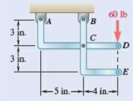
Fig. P6.87
SOLUTION
Free body: Entire frame:
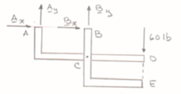
Analysis is valid for either parts (a) or (b), since position of 60-lb load on its line of action is immaterial.
 ∑MB = 0: − Ay (5 in.) – (60 lb)(4 in.) = 0 Ay = −48 lb
+↑ ∑Fy = 0: By − 60 − 480 = 0 By = +108 lb
 ∑Fx = 0: Ax + Bx = 0 (1)
a) Load applied at D.
Since BCE is a two-force member (with forces applied at B and C only), the reaction at B must be directed along CB. We have, therefore,
Bx = 0
The reaction at B is B = 108.0 lb↑
From Eq. (1): Ax + 0 = 0 Ax = 0
The reaction at A is A = 48.0 lb↓
(b) Load applied at E.
Since ACD is a two-force member, the reaction at A must be directed along AC. We have
From Eq. (1): 80 lb + Bx = 0 Bx = 80 lb
Thus, Bx = 80.0 lb ←, By = 108.0 lb ↑
Want to see the full answer?
Check out a sample textbook solution
Chapter 6 Solutions
Vector Mechanics for Engineers: Statics
Additional Engineering Textbook Solutions
Mechanics of Materials (10th Edition)
Fundamentals of Heat and Mass Transfer
Vector Mechanics for Engineers: Statics, 11th Edition
Statics and Mechanics of Materials (5th Edition)
Heat and Mass Transfer: Fundamentals and Applications
Applied Statics and Strength of Materials (6th Edition)


- 2. A 200-mm lever and a 240-mm pulley are welded to the axel BE that is supported by bearings at C and D. Assume that the bearing at D does not exert any axial thrust. A 720-N vertical force is applied at A when the lever is horizontal. Determine (a) the tension, T, in the cord, and (b) the reactions at C and D. Ans: T = 1200N, C = 400î +1200 N, D=-1600î – 480ĵ N %3D 40 mm 80 mm 120 mm 200 mm D E 120 mm 720 Narrow_forward4.7 When cars C and D stop on a two-lane bridge, the forces exerted by their tires on the bridge are as shown. Determine the total reactions at A and B when (a) a = 2.9 m, (b) a = 8.1 m. -12 m 3.9 kN 6.3 kN| 7.9 kN 7.3 kN C D\B A L-20m-| -2.6 m→ -2.8 marrow_forward2. Determine the reactions at A and B when (a) a = 0, (b) a = 90°, (c) a = 30°. 12 in. 10 in. 10 in. 750 lb in Barrow_forward
- Three cylinders are piled in a rectangular ditch as shown, neglecting friction. Wa=15lb, Wb=40lb and Wc=20lb. Determine reaction between cylinder A and the floor, reaction between cylinder A and wall, reaction between cylinder A and cylinder B, reaction between cylinder B and cylinder C, reaction between cylinder B and the wall, and reaction between cylinder C and the wall.arrow_forwardQuestion 1 (Type B): A 100 N boom is supported by a pin at A and a cable at C. Determine the magnitudes of the components of the reaction at A and the tension in the cable CD. D 50° 12 kN/m B -3 m 1 marrow_forwardProblem 4.30 4.30 The horizontal force P is applied to the handle of the puller. Determine the resulting tension T and all the other reactions as necessary. P = 120 lb Coplanar system, one rigid body, two supports, one 24 in. external load. B В 40° 20° A -6 in.-arrow_forward
- Knowing that for the rod of Prob. 4.89, L = 15 in., R = 20 in., and W = 10 lb, determine (a) the angle 0 corresponding to equilibrium, (b) the reactions at A and B.(Reference to Problem 4.89):A slender rod with a length of L and weight W is attached to a collar at A and is fitted with a small wheel at B . Knowing that the wheel rolls freely along a cylindrical surface of radius R , and neglecting friction, derive an equation in 0, L, and that must be satisfied when the rod is in equilibrium.arrow_forwardThree loads are applied to a beam as shown. The beam is supported by a roller at A and by a pin at B. Neglecting the weight of the beam, determine the reactions at A and B when P = 15 kips 6 kips 6 kips B 6 ft 3 ft 2 ft ' 2 ftarrow_forwardThe lid of a roof scuttle weighs 75 lb. It is hinged at corners A and B and maintained in the desired position by a rod CD pivoted at C; a pin at end D of the rod fits into one of several holes drilled in the edge of the lid. For α=50°, determine (a) the magnitude of the force exerted by rod CD, (b) the reactions at the hinges. Assume that the hinge at B does not exert any axial thrust.arrow_forward
- Fundamental Problem 5.9 The rod is supported by smooth journal bearings at A, B, and C and is subjected to the two forces F₁ = 400 N and F2 = 570 N. (Figure 1) Figure 1 0.6 m of 1 0.6 m BF₂ D 0.6 m 0.4 m F₁ Part A Determine the x and y components of reaction at C using scalar notation. Express your answers using three significant figures separated by a comma. V ΑΣΦ ↓↑ vec Cr, Cy= Submit B₂, B₂ = Part B Determine the x and z components of reaction at B using scalar notation. Express your answers using three significant figures separated by a comma. My Answers Give Up Az, Az = Submit VE ΑΣΦ | 11 |¯| ΑΣΦ ↓↑ vec Part C Determine the x and z components of reaction at A using scalar notation. Express your answers using three significant figures separated by a comma. My Answers Give Up ? vec E ? N N Narrow_forwardFundamentals of BlUmUT If the diving board has a total weight of 1500 N, determine the reactions on the beam at points A and D. Answers: RA 2318 N (1) Rp = 4602N (1) Problem 4.3 The uniform, horizontal beam shown in Fig. 4.50 is hinged to the ground at point A and supported by a friction- less roller at point D. The distance between points A and B is 1 = 4 m and the distance between points A and D is d = 3 m. A force that makes an angle B= 60° with the horizontal is applied at point B. The magnitude of the applied force is P = 1000 N. The total weight of the beam is W = 400 N. %3D d A By noting that three-quarters of the beam is on the left of the roller support and one-quarter is on the right, calculate the x and y components of reaction forces on the beam at points A and D. Fig. 4.50 Problem 4.3 Answers: Rp = 1421 N (↑) RAX 500N (-) RAy %3D 155N (1) %3D Problem 4.4 The uniform, horizontal beam shown in Fig. 4.51 is hinged to the wall at point A and supported by a cable attached to…arrow_forwardGoogle Lens Q2/ Knowing that the forces values given as: F1=32 N , F2=45 N , F3=60 N , *1=0.7 m , x2=0.4m , H=1.5m.a) Determine the x components of reactions at fixed support point Aarrow_forward
 Elements Of ElectromagneticsMechanical EngineeringISBN:9780190698614Author:Sadiku, Matthew N. O.Publisher:Oxford University Press
 Mechanics of Materials (10th Edition)Mechanical EngineeringISBN:9780134319650Author:Russell C. HibbelerPublisher:PEARSON
 Thermodynamics: An Engineering ApproachMechanical EngineeringISBN:9781259822674Author:Yunus A. Cengel Dr., Michael A. BolesPublisher:McGraw-Hill Education
 Control Systems EngineeringMechanical EngineeringISBN:9781118170519Author:Norman S. NisePublisher:WILEY
 Mechanics of Materials (MindTap Course List)Mechanical EngineeringISBN:9781337093347Author:Barry J. Goodno, James M. GerePublisher:Cengage Learning
 Engineering Mechanics: StaticsMechanical EngineeringISBN:9781118807330Author:James L. Meriam, L. G. Kraige, J. N. BoltonPublisher:WILEY