
Concept explainers
Videos
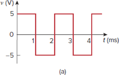
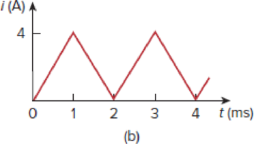
A square-wave generator produces the voltage waveform shown in Fig. 6.94(a). What kind of a circuit component is needed to convert the voltage waveform to the triangular current waveform shown in Fig. 6.94(b)? Calculate the value of the component, assuming that it is initially uncharged.
Figure 6.94
For Prob. 6.85.
Find the circuit component that is needed to convert the voltage waveform into the triangular current waveform and to calculate the value of the circuit component.
Answer to Problem 85CP
The circuit component inductor is needed to convert the given voltage waveform into the triangular current waveform and the value for the inductor
Explanation of Solution
Given data:
Refer to Figure 6.94 in the textbook.
Formula used:
Write the expression to calculate the straight line equation for two points
Refer to Figure 6.94(b) in the textbook.
From the given graph, substitute
Calculation:
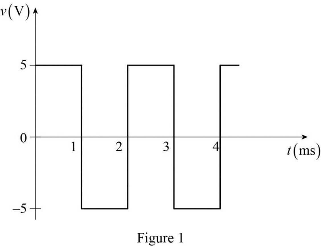
The given voltage waveform is redrawn as Figure 1.
The given triangular current waveform is redrawn as Figure 2.
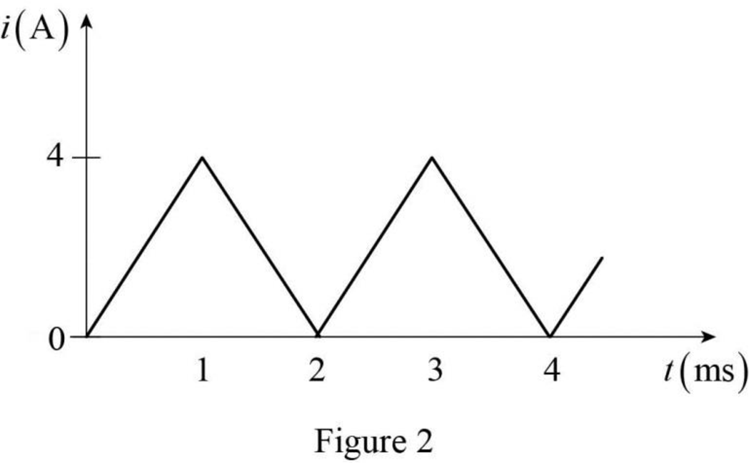
Refer to Figure 1 and Figure 2. Generally, integration of the square waveform gives the triangular waveform. That is, the integration of the voltage waveform gives the current waveform. Such relation can be obtained in following relation.
Here,
Refer to equation (3), the circuit component inductor is needed to convert the square voltage waveform to the triangular current waveform.
Differentiate the equation (3) with respect to
Rearrange the above equation to find
Refer to Figure 1. The voltage function is expressed as,
Refer to Figure 2, split up the time period as four divisions
Case (i):
The two points
Substitute
Simplify the equation to find
Case (ii):
The two points
Substitute
Simplify the equation to find
Case (iii):
The two points
Substitute
Simplify the equation to find
Case (iv):
The two points
Substitute
Simplify the equation to find
Therefore, the current function of the signal in Figure 2 is,
For
Substitute
For
Substitute
For
Substitute
For
Substitute
Therefore, the voltage function of the Figure 2 is expressed as,
The voltage function of the signal in Figure 1 is equal to the voltage function that is obtained in equation (6).
Compare the equations (5) and (6) for any of the time limits. Assume the comparison is made for
Rearrange the above equation to find
Therefore, the circuit component inductor is needed to convert the given voltage waveform into the triangular current waveform and the value for the inductor
Conclusion:
Thus, the circuit component inductor is needed to convert the given voltage waveform into the triangular current waveform and the value for the inductor
Want to see more full solutions like this?
Chapter 6 Solutions
EBK FUNDAMENTALS OF ELECTRIC CIRCUITS


- 3. 6.1.9 The voltage across a 50-µF capacitor is shown in Figure below. Determine the current waveform. v(1) (V) 4 Fot 2 10 -10 DO 8 10 I I I 12 (ms)arrow_forward57. A capacitor of capacitance 2 µF is charged to a potential difference of 200 V. After disconnecting from the battery, it is con- nected in parallel with another uncharged capacitor. The common potential is 40 V. The capacitance of the second capacitor is (i) 6 µF (ii) 12 µF (iii) 8 µF (iv) 16 µFarrow_forwardAn inductor of 5 mH has a voltage across it of 180e-12tmV. Its current at time 0 is i(0) = 10 A. Calculate its current at t = 50 ms.arrow_forward
- A resistance of 12 ohms and capacitance of 0.01 farad is connected in series with a 200 volts battery. Find the charge after 0.5 second and the current after 0.4 secondarrow_forward7. Calculate the component currents and loop voliages for the circuit shown in Figur- 6.44, along with the values of I7 and Rp. R, 470 N A 100 n R3 510 N R4 1 kn As 1.5 kn FIGURE 6.44 allel Circuitsarrow_forwardAn inductor draws 5A of current at 110V, 60hz. Express the instantaneous voltage and current mathematically. 4. The voltage across a 0.5H inductor is v=200 sin 100t V. What is the instantaneous current?arrow_forward
- Find the equivalent inductance. Assume all inductors are 10mHarrow_forwardIncreasing the inductance value in an a.c. inductive circuit will increase the circuit current. Select one: O True O Falsearrow_forwardInductors are fundamental components in electronics and electrical circuits. They are passive devices that store energy in the form of a magnetic field when crossed by an electric current. Inductors consist of a wire wound around a core, often made of iron or another ferromagnetic material. The storage of magnetic energy in inductors is expressed in terms of inductance, measured in henries (H). What is the value of inductive reactance (XL) in ΩΩ, exhibited by the inductor in the circuit below?arrow_forward
- A 10mH inductor was supplied by a 6et/2A current. What will be its voltage after 2 seconds of being charged? -0.01 volts -2.45 v O-4.45 mV -6.69 mVarrow_forwardCalculate the equivalent inductance of the circuit if the 6-mH inductor and the combination of 8-mH and 10-mH inductors in parallel (no coupling between them) are series opposing at 40% coupling.* O 1.7mH O 2.07mH O 7.07mH O 8.37mHarrow_forward
 Introductory Circuit Analysis (13th Edition)Electrical EngineeringISBN:9780133923605Author:Robert L. BoylestadPublisher:PEARSON
 Delmar's Standard Textbook Of ElectricityElectrical EngineeringISBN:9781337900348Author:Stephen L. HermanPublisher:Cengage Learning
 Programmable Logic ControllersElectrical EngineeringISBN:9780073373843Author:Frank D. PetruzellaPublisher:McGraw-Hill Education
 Fundamentals of Electric CircuitsElectrical EngineeringISBN:9780078028229Author:Charles K Alexander, Matthew SadikuPublisher:McGraw-Hill Education
 Electric Circuits. (11th Edition)Electrical EngineeringISBN:9780134746968Author:James W. Nilsson, Susan RiedelPublisher:PEARSON
 Engineering ElectromagneticsElectrical EngineeringISBN:9780078028151Author:Hayt, William H. (william Hart), Jr, BUCK, John A.Publisher:Mcgraw-hill Education,