
Videos
The current waveform in Fig. 6.80 flows through a 3-H inductor. Sketch the voltage across the inductor over the interval 0 < t < 6 s.
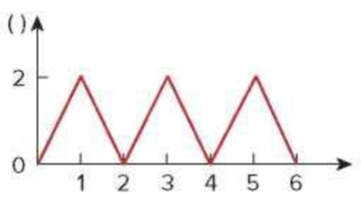
Figure 6.80
For Prob. 6.58.
Sketch the voltage across the inductor over the interval
Explanation of Solution
Given data:
The value of the inductor
Refer to Figure 6.80 in the textbook.
Formula used:
Write the expression to calculate the straight line equation for two points
Refer to Figure 6.80 in the textbook.
From the given graph, substitute
Write the expression to calculate the voltage across the inductor.
Here,
Calculation:
The given current waveform is redrawn as Figure 1.
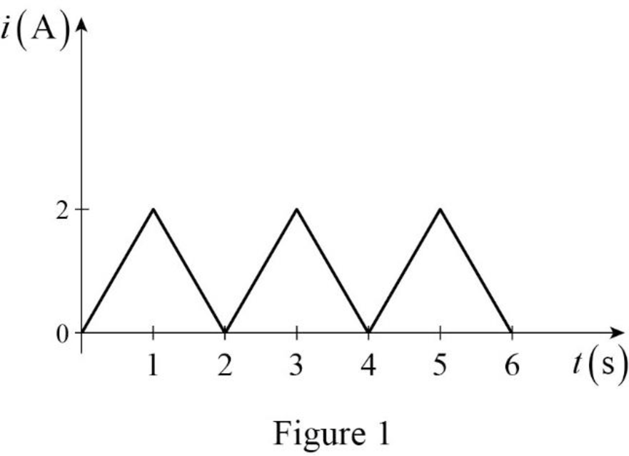
Refer to Figure 1, split up the time period as six divisions
Case (i):
The two points
Substitute
Simplify the equation to find
Case (ii):
The two points
Substitute
Simplify the equation to find
Case (iii):
The two points
Substitute
Simplify the equation to find
Case (iv):
The two points
Substitute
Simplify the equation to find
Case (v):
The two points
Substitute
Simplify the equation to find
Case (vi):
The two points
Substitute
Simplify the equation to find
Therefore, the current function of the signal in Figure 1 is,
For
Substitute
For
Substitute
For
Substitute
For
Substitute
For
Substitute
For
Substitute
The expression of the voltage
From the voltage expression, the signal is drawn in Figure 2.
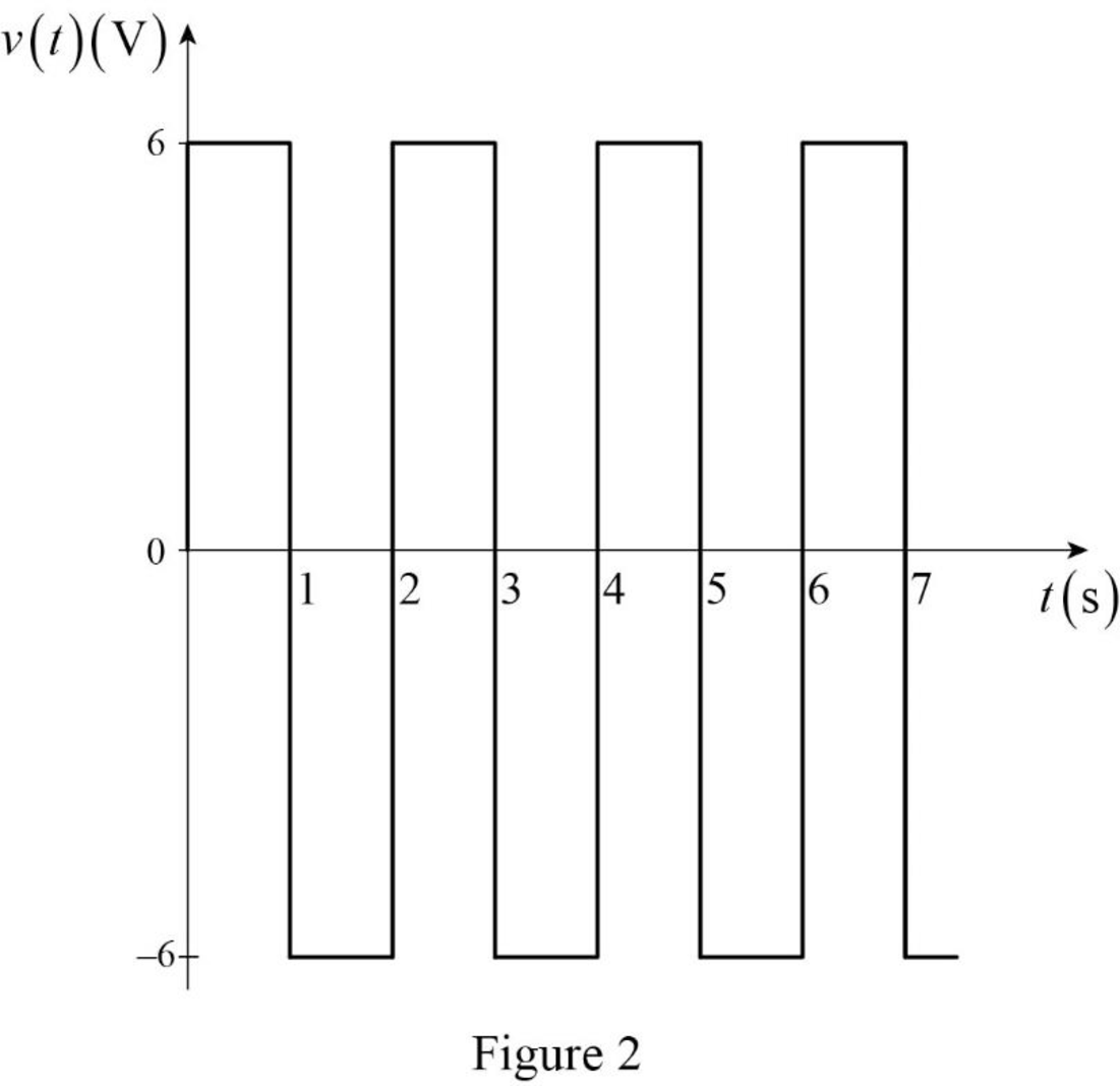
Conclusion:
Thus, the voltage across the inductor over the interval
Want to see more full solutions like this?
Chapter 6 Solutions
EBK FUNDAMENTALS OF ELECTRIC CIRCUITS


- A 20-mH inductor and a 18-mH inductor are connected in series with a 3-A current source. Find (a) the equivalent inductance and (b) the total energy stored. (a) mH (b) mJarrow_forwardstc ksa l. A bartleby.com 6.53 Find Leg at the terminals of the circuit in Fig. 6.75. 6 mH 8 mH ell 5 mH a o m 12 mH 8 mH 6 mH 4 mH ell bo m 10 mH 8 mH Figure 6.75 For Prob. 6.53. llarrow_forward6.53 Find Leg at the teminals of the circuit in Fig. 6.75. 6 mH 8 mH a o all 5 mH 12 mH 8 mH 6 mH 4 mH bomm 10 mH 8 mHarrow_forward
- 6.48 Under steady-state dc conditions, find i and v in the circuit in Fig. 6.71. 5 mA Figure 6.71 For Prob. 6.48. i 2mH 30 ΚΩ 20 ΚΩ 6 μF Iarrow_forwardThe R-L Circuit: An inductor with an inductance of 2.50 H and a resistance of 7.00 n is connected to the terminals ofa battery with an emf of 6.00 V and an internal resistance of 1.00 n. What is the rate ofincrease of current at the instant when the current is 0.500 A? A) 0.8 A/s B) 0.6 A/s C) 0.4 A/s D) zero E) None of the above.arrow_forwardEXAMPLE 6. The waveform for the current in a 1nF capacitor is shown. If the capacitor has an initial voltage of -5 V, determine the waveform for the capacitor voltage. How much energy is stored in the capacitor at t = 6 ms? 10 10 -10 -10 10 12 time (ms) (micro- 2.arrow_forward
- 1. The current through a 5-F capacitor is 6(1 - e2) A. Determine the voltage and power at = 2 s. Assume v(0) = 0.arrow_forwardThe current through a 10-mH inductor is 10e-12 A. Find the voltage and the power at t = 2 s. The voltage is The power is mV mW Aarrow_forwardA 2002 resistor, a 0.01 H inductor and a 100 µF capacitor are connected in series, A DC voltage of 100 V is suddenly applied to the circuit. Find the maximum current and the time at which it occurs.arrow_forward
- The initial voltage drop across capacitor is 40V and R-500 Ohm Find the current ic(0+).arrow_forward-2•t mA (tis in 6.32 In the circuit below, the source current function is ig = 4.0.e second in this equation), and the voltage across each capacitor is equal to zero at t = 0. The capacitors = 21 UF , C2 = 13 UF , and C3 = 14 UF. Determine the v2 (in V) when t = 1.3 s. Please pay attention: the numbers may change since they are randomized. Your answer must include 1 place after the decimal point. %3D %3D %3D C3 + is V2 C2 10 Ω Your Answer: Answerarrow_forward6.46 Find vc, i̟, and the energy stored in the capacit and inductor in the circuit of Fig. 6.69 under de conditions. + "C = 2 F 6A 0.5 H Figure 6.69 For Prob. 6.46. wwarrow_forward
 Introductory Circuit Analysis (13th Edition)Electrical EngineeringISBN:9780133923605Author:Robert L. BoylestadPublisher:PEARSON
 Delmar's Standard Textbook Of ElectricityElectrical EngineeringISBN:9781337900348Author:Stephen L. HermanPublisher:Cengage Learning
 Programmable Logic ControllersElectrical EngineeringISBN:9780073373843Author:Frank D. PetruzellaPublisher:McGraw-Hill Education
 Fundamentals of Electric CircuitsElectrical EngineeringISBN:9780078028229Author:Charles K Alexander, Matthew SadikuPublisher:McGraw-Hill Education
 Electric Circuits. (11th Edition)Electrical EngineeringISBN:9780134746968Author:James W. Nilsson, Susan RiedelPublisher:PEARSON
 Engineering ElectromagneticsElectrical EngineeringISBN:9780078028151Author:Hayt, William H. (william Hart), Jr, BUCK, John A.Publisher:Mcgraw-hill Education,