
Concept explainers
Videos
If v(0) = 0, find v(t), i1(t), and i2(t) in the circuit of Fig. 6.63.
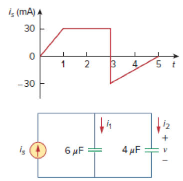
Figure 6.63
For Prob. 6.31.
Find the expression for voltage
Answer to Problem 31P
The expression of voltage
Explanation of Solution
Given data:
Refer to Figure 6.63 in the textbook.
The initial voltage at time
Formula used:
Write the expression to calculate the straight line equation for two points
Refer to Figure 6.63 in the textbook.
From the given graph, substitute
Write the expression to calculate the voltage across the capacitor.
Here,
Calculation:
The given circuit is redrawn as Figure 1.
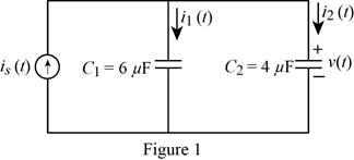
Refer to Figure 1, the capacitors
Write the expression to calculate the equivalent capacitance for the parallel connected capacitors
Here,
Substitute
The given current waveform is redrawn as Figure 2.
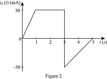
Refer to Figure 2, split up the time period as three divisions
Case (i):
The two points
Substitute
Simplify the equation to find
Case (ii):
The two points
Substitute
Simplify the equation to find
Case (iii):
The two points
Substitute
Simplify the equation to find
Therefore, the current function of the signal in Figure 2 is,
For
Substitute
Simplify the equation to find
Substitute
For
Write the expression to calculate the capacitor voltage depends on the past history of the capacitor voltage.
Here,
Substitute
Simplify the equation to find
Substitute
For
Write the expression to calculate the capacitor voltage depends on the past history of the capacitor voltage.
Here,
Substitute
Simplify the equation to find
Simplify the equation to find
Therefore, the expression of the voltage
Write the expression to calculate the current through the capacitor
For
Substitute
Simplify the equation to find
For
Substitute
Simplify the equation to find
For
Substitute
Simplify the equation to find
Therefore, the expression of current through the capacitor
Write the expression to calculate the current through the capacitor
For
Substitute
Simplify the equation to find
For
Substitute
Simplify the equation to find
For
Substitute
Simplify the equation to find
Therefore, the expression of current through the capacitor
Conclusion:
Thus, the expression of voltage
Want to see more full solutions like this?
Chapter 6 Solutions
EBK FUNDAMENTALS OF ELECTRIC CIRCUITS


- The voltage across a 4-µF capacitor is shown in Fig. 6.45. Find the current waveform. v(t) V 4 10 6. I (ms) -10arrow_forwardLea 7. Figure 6.73 For Prob. 6.48.arrow_forwardIf the voltage waveform in Fig. 6.68 is applied to a 50-mH inductor, find the inductor current i(t). Assume i(0) = 0. v(t) (V) 10 1 -10 Figure 6.68arrow_forward
- 2. Determine the Therenin's nd Horton's equivalent for each of the circuits shown below with respect to terminals a and b. (a) C) 6A (6) (d) ea CAarrow_forward18.6.31 If v(0) = 0, find v(t), i, (t), and i2(t) in the circuit of Fig. 6.63. is (mA) A 30 O -30 is 4 1 2 I 6 μF = Figure 6.63 For Prob. 6.31. 3 4 LO 5 +21 4 μF = v tarrow_forward6.19 Obtain the equivalent capacitance of the circuit in Fig. 6.54. 35 μF Figure 6.54 40 μF 10 μF 10 μF 20 μF 15 μF 15 μF For Prob. 6.19. b 5 μF HHarrow_forward
- 6.51 Detemine Leq at terminals a-b of the circuit in Fig. 6.73. 10 mH all 60 mH 25 mH 20 mH a o 30 mH llarrow_forwardElectrical Engineering Find 'v' for the circuit below 6Rarrow_forwardProblem 6 a) Determine the equivalent inductance of the following circuit 10 mH ll 60 mH 25 mH 20 mH 30 mH ll b) An electric motor can be modeled as a series combination of a 120 resistor and a 200mH inductor. A current i(t) = 2te-10t A t > Os flows through this series combination. Find the voltage v(t) across this series combination for t > Os R1 i(t) L1 v(t)arrow_forward
- A) Reduce the given circuit to the fewest possible componentsthru series/parallel combinationsB) DetermineVx if all resistors are 10k , all capacitors are 50uF and all inductors are 1mHarrow_forwardThe R-L Circuit: An inductor with an inductance of 2.50 H and a resistance of 7.00 n is connected to the terminals ofa battery with an emf of 6.00 V and an internal resistance of 1.00 n. What is the rate ofincrease of current at the instant when the current is 0.500 A? A) 0.8 A/s B) 0.6 A/s C) 0.4 A/s D) zero E) None of the above.arrow_forward1) A DC circuit has as a load. (a) Resistance (b) Inductance (c) Capacitance (d) All of the abovearrow_forward
 Introductory Circuit Analysis (13th Edition)Electrical EngineeringISBN:9780133923605Author:Robert L. BoylestadPublisher:PEARSON
 Delmar's Standard Textbook Of ElectricityElectrical EngineeringISBN:9781337900348Author:Stephen L. HermanPublisher:Cengage Learning
 Programmable Logic ControllersElectrical EngineeringISBN:9780073373843Author:Frank D. PetruzellaPublisher:McGraw-Hill Education
 Fundamentals of Electric CircuitsElectrical EngineeringISBN:9780078028229Author:Charles K Alexander, Matthew SadikuPublisher:McGraw-Hill Education
 Electric Circuits. (11th Edition)Electrical EngineeringISBN:9780134746968Author:James W. Nilsson, Susan RiedelPublisher:PEARSON
 Engineering ElectromagneticsElectrical EngineeringISBN:9780078028151Author:Hayt, William H. (william Hart), Jr, BUCK, John A.Publisher:Mcgraw-hill Education,