
Applied Fluid Mechanics (7th Edition)
7th Edition
ISBN: 9780132558921
Author: Robert L. Mott, Joseph A. Untener
Publisher: PEARSON
expand_more
expand_more
format_list_bulleted
Concept explainers
Videos
Textbook Question
Chapter 6, Problem 6.55PP
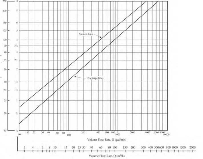
For Problems 6.55-6.57, use Fig. 6.3 O to specify suitable Schedule 40 pipe sizes for carrying the given volume flow rate of water in the suction line and in the discharge line of a pumped distribution system. Select the pipe sizes both above and below the curve for the given flow rate| and then calculate the actual velocity of flow in each.
| Suction Line |
Expert Solution & Answer
Want to see the full answer?
Check out a sample textbook solution
Students have asked these similar questions
A 400 gpm piping system is composed of the following pipes and fittings.
Using the chart;
Determine the Following:
a. Equivalent length at suction in ft
b. Equivalent length at discharge in ft
c. Total friction loss in the installation, in ft.
Suction side (4.5” Փ)
Length of straight pipe 210 ft
Long sweep elbow 5 pcs
Standard Tee 2 pcs
Globe valve 1 pc
Checked valve 1 pc
Gate valve (fully open) 1 pc
Discharge side (4.0” Փ)
Straight pipe 200 ft
Standard elbow 4 pcs
Standard Tee 3 pcs
Gate valve (fully open) 1 pc
8. A pumped fluid distribution system is being designed to deliver 400 gal/min of water to a
cooling system in a power generation plant. Use the figure below to make an initial selection
of Schedule 40 pipe sizes for the suction and discharge lines for the system. Also, solve for
the actual average velocity of flow for each pipe.
DN (mm) NPS (in)
250
200
150 -
125 -
Suction lines
100 -
90 -
3
65 -
2
50
Discharge lines
40
32E
25 E
15 20
200
400
600 800
1000
2000
4000
6000 8000
10000
10
100
Volume Flow Rate, Q (gal/min)
6 8 10
++++
15 20 25 30 40
+++++++++ ++++++++++++
60
80 100
150 200
300 400 500600 800 1000 1200 2000
Volume Flow Rate, Q (m/h)
8. A pumped fluid distribution system is being designed to deliver 400 gal/min of water to a
cooling system in a power generation plant. Use the figure below to make an initial selection
of Schedule 40 pipe sizes for the suction and discharge lines for the system. Also, solve for
the actual average velocity of flow for each pipe.
DN (mm) NPS (in)
250
200-
150 -
6
125-
Suction lines
100 -
4
3.
65
2
50E
2
Discharge lines
40 -
32 -
25 E
15
15 20
30 40
60
200
400
600 S00
2000
4000
6000 S00
80
100
10
Volume Flow Rate, Qallmin)
8 10
15
20 25 30 40
+++++ +++
60
80 100
150 200
300 400 500600 800 1000 1200
2000
+++++ +++++
Volame Flow Rate, Q (mVh)
Chapter 6 Solutions
Applied Fluid Mechanics (7th Edition)
Ch. 6 - Convert a volume flow rate of 3.0 gal/min to...Ch. 6 - Convert 459 gal/min to rrP/s.Ch. 6 - Convert 3720 gal/min to mJ/sCh. 6 - Convert 34.3 gal/min to mJ/sCh. 6 - Convert a volume flow rate of 125 L/min to m3/s.Ch. 6 - Convert 4500 L/min to m5/s.Ch. 6 - Convert 15 000 L/minto m3/s.Ch. 6 - Convert 459 gal/min to L/mninCh. 6 - Convert 3720 gal/min to L/minCh. 6 - Convert 23.5cm2/stom3/s.
Ch. 6 - '6.11 Convert 0.296cm5/stom3/s.Ch. 6 - Convert 0.105 cm3/s to L/minCh. 6 - Convert 3.53103m3/s to L/min.Ch. 6 - Convert 5.26106m3stoL/min.Ch. 6 - Prob. 6.15PPCh. 6 - Convert 20 gal/min to ft'/s.Ch. 6 - Convert 2500 gal/min to ft5/s.Ch. 6 - Convert 2.50 gal/min to ft3/s.Ch. 6 - Convert 125 ft3/s to gal/minCh. 6 - Convert 0.060 ft3/s to gal/min.Ch. 6 - Convert 0.03 ft5/s to gal/minCh. 6 - Convert ft5/s sto gal/minCh. 6 - Table 6.21 lists the range of typical volume flow...Ch. 6 - Table 6.2 lists the range of typical volume flow...Ch. 6 - A certain deep-well pump for a residence is rated...Ch. 6 - A small pump delivers 0.85 gal/h of liquid...Ch. 6 - A small metering pump delivers 11.4 gal of a water...Ch. 6 - A small metering pump delivers 19.5 mL/min of...Ch. 6 - Water at 10 C is flowing at 0.075 m3/s Calculate...Ch. 6 - Oil for a hydraulic system (sg =0.90 ) is flowing...Ch. 6 - A liquid refrigerant (sg = 1.08) is flowing at a...Ch. 6 - After the refrigerant from Problem 6.31 flashes...Ch. 6 - A fan delivers 640ft3/min (CFM) of air. If the...Ch. 6 - A large blower for a furnace delivers 47000ft3/min...Ch. 6 - A furnace requires 1200 Ib/h of air for efficient...Ch. 6 - If a pump removes 1.65 gal/min of water from a...Ch. 6 - Calculate the diameter of a pipe that would carry...Ch. 6 - If the velocity of a liquid is 1.65 ft/s in a...Ch. 6 - When 2000 L/min of water flows through a circular...Ch. 6 - Water flows at 1.20 m/s in a circular section with...Ch. 6 - Figure 6.16 shows a fabricated assembly made from...Ch. 6 - A standard Schedule 40 steel pipe is to be...Ch. 6 - If water at 180 F is flowing with a velocity of...Ch. 6 - A standard steel tube, 1.5 25-mm OD 3 1,5-mm wall...Ch. 6 - The recommended velocity of flow in the discharge...Ch. 6 - Repeat Problem 6.45, except specify suitable sizes...Ch. 6 - Table 6.2 shows the typical volume flow rate for...Ch. 6 - Repeat Problem 6.47 but use Schedule 80 DM pipeCh. 6 - Compute the resulting velocity of flow if 400...Ch. 6 - Repeat Problem 6.49 for a DN 50 Schedule 30 pipe.Ch. 6 - Compute the resulting velocity of flow if 400...Ch. 6 - Repeat Problem 6.51 for a 4-in Schedule 30 pipe.Ch. 6 - From the list of standard hydraulic steel tubing...Ch. 6 - A standard 6-in Schedule 40 steel pipe is carrying...Ch. 6 - For Problems 6.55-6.57, use Fig. 6.3 O to specify...Ch. 6 - For Problems 6.55-6.57, use Fig. 6.3 to specify...Ch. 6 - For Problems 6.55-6.57, use Fig. 6.3 O to specify...Ch. 6 - A venturi meter is a device that uses a...Ch. 6 - A flow nozzle, shown in Fig. 6.18 is used to...Ch. 6 - Gasoline (sg = 0.67) is flowing at 0.11 m3/s in...Ch. 6 - Water at 10 C is flowing from point A to point B...Ch. 6 - Calculate the volume flow rate of water at 5 C...Ch. 6 - Calculate the pressure required in the larger...Ch. 6 - Kerosene with a specific weight of 50.0 lb/ft3 is...Ch. 6 - For the system shown in Fig. 6.23 ; calculate (a)...Ch. 6 - For the system shown in Fig. 6.24ss, calculate (a)...Ch. 6 - For the tank shown in Fig. 6.25lO, calculate the...Ch. 6 - Calculate the pressure of the air in the sealed...Ch. 6 - For the siphon in Fig. 6.26, calculate (a) the...Ch. 6 - For the siphon in Fig. 6.26 , calculate the...Ch. 6 - For the siphon in Fig. 6.26 , assume that the...Ch. 6 - For the siphon shown in Fig. 6.27, calculate (a)...Ch. 6 - For the special fabricated reducer shown in Fig....Ch. 6 - In the fabricated enlargement shown in Fig. 6.29,...Ch. 6 - Figure 6.30 shows a manometer being used to...Ch. 6 - For the venturi meter shown in Fig. 6.30,...Ch. 6 - Oil with a specific weight of 8.64 kN/m3 flows...Ch. 6 - The venturi meter shown in Fig. 6.32 iP carries...Ch. 6 - Oil with a specific gravity of 0.90 is flowing...Ch. 6 - Oil with a specific gravity of 0.90 is flowing...Ch. 6 - Gasoline (sg = 0.67) is flowing at 4.0 ft3/s in...Ch. 6 - Oil with a specific weight of 55.0lb/ft3 flows...Ch. 6 - Draw a plot of elevation head, pressure head,...Ch. 6 - Prob. 6.84PPCh. 6 - Figure 6.36 shows a system in which water flows...Ch. 6 - Figure 6.37 shows a venturi meter with a U-tube...Ch. 6 - For the tank shown in Fig. 6.38, compute the...Ch. 6 - What depth of fluid above the outlet nozzle is...Ch. 6 - Derive Torricelli's theorem for the velocity of...Ch. 6 - Solve Problem 6.88 using the direct application of...Ch. 6 - To what height will the jet of fluid rise for the...Ch. 6 - To what height will the jet of water rise for the...Ch. 6 - What pressure is required above the water in Fig....Ch. 6 - What pressure is required above the water in Fig....Ch. 6 - Compute the time required to empty the tank shown...Ch. 6 - Compute the time required to empty the tank shown...Ch. 6 - Compute the time required to empty the tank shown...Ch. 6 - Compute the time required to empty the tank shown...Ch. 6 - Compute the time required to reduce the depth in...Ch. 6 - Compute the time required to reduce the depth in...Ch. 6 - Compute the time required to reduce the depth in...Ch. 6 - Compute the time required to reduce the depth in...Ch. 6 - Prob. 6.103PPCh. 6 - Repeat Problem 6.101 if the tank is sealed and a...Ch. 6 - Repeat Problem 6.96 if the tank is sealed and a...Ch. 6 - Repeat Problem 6.100 if the tank is sealed and a...Ch. 6 - A village currently carries water by hand from a...Ch. 6 - A "spa tub" is to be designed to replace bath tubs...Ch. 6 - A simple soft drink system relies on pressurized...Ch. 6 - A concept team for a toy company is considering a...Ch. 6 - 6.111 Bernoulli's principle applies to Venturi...Ch. 6 - Prob. 6.112PPCh. 6 - You are to develop a mixing valve for use in a...Ch. 6 - Prob. 6.114PPCh. 6 - You would like to empty the in-ground pool in the...Ch. 6 - Prob. 6.116PPCh. 6 - Create a spreadsheet for computing the values of...Ch. 6 - Prob. 2APCh. 6 - Prob. 3APCh. 6 - Create a spreadsheet for computing, using Eq....Ch. 6 - Prob. 5APCh. 6 - Create a spreadsheet for computing the velocity of...
Knowledge Booster


Learn more about
Need a deep-dive on the concept behind this application? Look no further. Learn more about this topic, mechanical-engineering and related others by exploring similar questions and additional content below.Similar questions
- Use g=32.2 */sec2 (9.81 m/s2) and 60°F (16°C) water unless told to do otherwise.• Google schedule-40 pipe’s thickness at different nominal size to obtain the innerdiameter of the pipe for accurate determinaLon of flow velocity.• Must show your work to support your selecLon. Otherwise, no points will be given.• No peer discussion is allowed.1. A schedule-40 pipe necks down from 24 in at point A to 12 in at point B. 8 *3/sec of 60°Fwater flow from point A to point B. The pressure head at point A is 20 *. FricLon is insignificantover the distance between points A and B. What are the magnitude and direcLon of theresultant force on the water? (A) 2900 lbf; toward A(B) 3500 lbf; toward A(C) 2900 lbf; toward B(D) 3500 lbf; toward Barrow_forward1. Specify the sizes of pipes (cast iron, schedule 40 ) and the size of the motor to be used for a pump to lift water at 50 from reservoir A to reservoir B. Consider the following data: Total static head Fittings and valves: Suction line Discharge line Length of straight pipe: Suction pipe Discharge pipe Absolute viscosity of water Absolute roughness of cast iron Water velocity 50 m 1 foot valve, 1 standard elbow 1 gate valve 1 check valve (same as close return valve), 1 gate valve, 1 long sweep elbow, 2 standard elbow 300 m 80 m 0.001002 Pa-s 0.00026 m m 1.18 -2.75 S Pump efficiency 80% Note: Neglect the head loss in the foot valve and at the pipe exit in the discharge reservoir and do not equal sizes for the suction and discharge pipes. Draw the piping system.arrow_forwardoblems: 1. A horizontal pipe, 1 ft. in diameter, tapers gradually to 8 in. in diameter. If the flow is 500 cu ft. of water per minute, what is the difference between the pressures at the two sections? Ans. PA - PB = 443.63lb per sq ft 2. Water flows through a horizontal pipe at a velocity of 50 ft. per sec. Owing to the pipe gradually expanding to a larger size, the velocity decreases to 35 ft. per sec. What is the difference between the pressures at two points, one in each size of pipe? Ans. Pg - PA = 1,236. 75 lb per sq ftarrow_forward
- 2. A main pipe GH branched into three pipes; HI, HJ and HK. A liquid flow with a flow rate of 25 liters/minute via piping HI. If the flowrate in the pipe GH is three times greater than the rate of flow in the pipe HJ and HI flow rate is 1.5 times less than the rate of flow in the pipe HJ. a. Calculate the flow rate in the main pipe GH. b. Get diameter pipes HK if the mean velocity in the pipe HK is 2.3 m/sarrow_forwardWater enters a pump through a 250 mm diameter and leaves the pump through a 150 mmdiameter pipe. If the flow rate is 150 li/s, compute the following:a. Velocity of suction pipe.b. Velocity of discharge pipe.arrow_forwardQUESTION 4 The figure below shows a fluid flow system that is designed to pump water at 20 °C from a lower vented reservoir to an elevated vented tank. Note that the drawing is not to scale as the dimensions of the reservoirs are very large relative to those of the piping system. The suction line entering the pump is specified as 20 m of 3½" schedule 40 commercial steel pipe; the discharge line from the pump is 180 m of 2%" schedule 40 commercial steel pipe. 15 m 3 m 31/2-in Schedule 40 steel pipe Fully open gate valve 21/2-in Schedule 40 steel pipe Flanged regular 90⁰ elbows Pump Flow Swing-type check valve valve Butterfly (K butterfly = 0.8) a. Starting from the Bernoulli equation (in 'head' form) for the situation where the liquid levels in the two reservoirs are reference points 1 and 2, derive the correct equation for pump head Hpump (m) in terms of volumetric flow rate Q (m³/s) and other process variables (e.g. z, f, L, D, K). b. Using Excel (or another suitable program), create…arrow_forward
- FROM THE ATTACHED SKETCH, THE GIVEN DATA ARE AS FOLLOWS: Pressure loss due to friction a. Reservoir tank =50,000 liters of water b. Total Static head is 30 ft. Pressure loss in plastic pipes (feet of water per 100 ft of tube) c. Pipe material is plastic and 1.5-inch diameter. d. There are four 90-degree elbows, one gate valve and one open swing spm 0.5 in. 0.75 in. 1 in. 1.5 in. 2 in. 3 in. 1.4 4.8 0.0 0.0 0.0 0.4 0.1 0.4 0.8 1.3 1.9 2.7 0,0 0.0 valve. 0.0 1.2 2.5 4.2 6.3 8.8 15.2 26.0 49.7 86.9 e. Total pipe length is 50 ft. 3 0.0 10.0 17.1 25.8 36.3 63.7 97.5 0.0 0.1 0.2 0.2 0.3 4. 0.0 0.0 5 0.0 0.0 0.0 0,0 0.0 6 0.1 0.2 0.3 0.5 0.9 0.1 COMPUTE THE FOLLOWING USING THE PROVIDED TABLE BELOW. 8 4.6 0.6 10 15 20 6.9 14.6 0.8 1.7 2.9 0.0 25.1 1. IF THE TANK IS TO BE FILLED WITHIN 661.35 MINUTES WHEN EMPTY, COMPUTE HOW MANY GALOONS PER MINUTE (GPM) PUMP CAPACITY IS NEEDED TO FILL UP THIS TANK., USE 3.78 LITERS/GAL Pressure loss in valves and elbows (expressed in equivalent length of tube)…arrow_forwardFor a 6.25-inch Model 4075 pump operated at 1160 rpm, if 450 GPM of water is to be delivered, what will be the estimated pump head in ft? HEAD IN FEET 30 25 0 0 0 10 O 6 ft 7.25" (184mm) 20 7.00" (178mm). 6.75" (171mm). 6.50" (165mm)] 15 6.25" (159mm). 5 O 16 ft O 20 ft O 12 ft aco® L/SEC 5 OT 10 Model 4075 FI & CI Series 15 -6-6 ⁰ dº 20 ANA 888 778 25 REQUIRED NPSH do 1160 RPM November 1, 2010 K ・dº- [M 90 do 30 8800 81 1HP(.75KW) DeJ kin do 60% 35 do 50 Curve no. 2175 Min. Imp. Dia. 6.25" Size 5 x 4 x 7.0 40 45 3HP(2.2KW), 2HP(1 5KW) 5HP(1 1KW)> CURVES BASED ON CLEAR WATER WITH SPECIFIC GRAVITY OF 1.0 L 75 150 225 300 375 450 525 600 675 FLOW IN GALLONS PER MINUTE NOWONG FEET 15 12 7 6 2 1 NPSH 758 50 5 HEAD IN METERS 45 586888 KPO 60 40 20 10 LO HEAD IN KILOPASCALSarrow_forwardQ2// Water is flowing through a (2 inch) diameter pipe with a velocity of 3 ft/sec. 1// wlaat is the kinetic energy of the water in (ft)(Ib/(Ib)? 2// what is the flow rate in gal/min?arrow_forward
- water flows through 30 mm internal diameter pipe at atmospheric pressure. pitot tube measures the velocity of water at the center of pipe as shown in the fig. the pressure difference between the impact tube and the static tube is 20cm of carbon tetrachloride (density: 1600 kg/m³). calculate the volumetric flow rate through the pipe in cubic meter per hour. velocity of water is cp.arrow_forwardA pumping system is required that will deliver at least 50,000 GPM against a head of 100 ft is needed for a water ride. The system schematic is given below. Note that the loss coefficient for the pumps accounts for the losses in piping connecting multiple pumps. Use Gould pumps to satisfy this requirement. Submit your loss curve superimposed on the pump curves for the selected pumps in your Excel file. Determine the following. a. The pumps (all the same) to satisfy this requirement. b. The operating point of these pumps. C. NPSHR d. NPSHA K, = 0.28 L, = 50 ft L = 300 ft E = 0.005 ft D = 3.5 ft Q=50,000 GPM u= 2.359x10⁵ slug/ft-s p= 1.938 slug/ft = 1.0 Kext 100 ft K, = 0.6 K, = 0.4 7 ft Pump System K, = 0.28 %3D Kant = 0.5arrow_forwardURGENT Please answer this problem in 30minutes. I need correct answers with complete and step by step solution. Box the final answers. Do not shortcut your solution. I will give an upvote if it satisfies. Thank you! If the velocity of water is 8 m/s and the pressure is 140 kPa on the discharge side of a pump. a. What is the head of the pump if the velocity is 4 m/s and the pressure is 90 kPa on the suction side of the pump? b. How much power is required to drive it if the diameter of the suction side is 600mm? c. If the pump is rated at 120hp, what is the efficiency of the pump neglecting energy losses in the system?arrow_forward
arrow_back_ios
SEE MORE QUESTIONS
arrow_forward_ios
Recommended textbooks for you
 Elements Of ElectromagneticsMechanical EngineeringISBN:9780190698614Author:Sadiku, Matthew N. O.Publisher:Oxford University Press
 Mechanics of Materials (10th Edition)Mechanical EngineeringISBN:9780134319650Author:Russell C. HibbelerPublisher:PEARSON
 Thermodynamics: An Engineering ApproachMechanical EngineeringISBN:9781259822674Author:Yunus A. Cengel Dr., Michael A. BolesPublisher:McGraw-Hill Education
 Control Systems EngineeringMechanical EngineeringISBN:9781118170519Author:Norman S. NisePublisher:WILEY
 Mechanics of Materials (MindTap Course List)Mechanical EngineeringISBN:9781337093347Author:Barry J. Goodno, James M. GerePublisher:Cengage Learning
 Engineering Mechanics: StaticsMechanical EngineeringISBN:9781118807330Author:James L. Meriam, L. G. Kraige, J. N. BoltonPublisher:WILEY
Elements Of Electromagnetics
Mechanical Engineering
ISBN:9780190698614
Author:Sadiku, Matthew N. O.
Publisher:Oxford University Press
Mechanics of Materials (10th Edition)
Mechanical Engineering
ISBN:9780134319650
Author:Russell C. Hibbeler
Publisher:PEARSON
Thermodynamics: An Engineering Approach
Mechanical Engineering
ISBN:9781259822674
Author:Yunus A. Cengel Dr., Michael A. Boles
Publisher:McGraw-Hill Education
Control Systems Engineering
Mechanical Engineering
ISBN:9781118170519
Author:Norman S. Nise
Publisher:WILEY
Mechanics of Materials (MindTap Course List)
Mechanical Engineering
ISBN:9781337093347
Author:Barry J. Goodno, James M. Gere
Publisher:Cengage Learning
Engineering Mechanics: Statics
Mechanical Engineering
ISBN:9781118807330
Author:James L. Meriam, L. G. Kraige, J. N. Bolton
Publisher:WILEY
Fluid Mechanics - Viscosity and Shear Strain Rate in 9 Minutes!; Author: Less Boring Lectures;https://www.youtube.com/watch?v=_0aaRDAdPTY;License: Standard youtube license