
Fluid Mechanics
8th Edition
ISBN: 9780073398273
Author: Frank M. White
Publisher: McGraw-Hill Education
expand_more
expand_more
format_list_bulleted
Concept explainers
Videos
Textbook Question
Chapter 6, Problem 6.128P
 In the five-pipe horizontal network of Fig. P6.127, as sume that all pipes have a friction factor f = 0.025. For the given inlet and exit glow rate of 2 ft3/s of water at 20°C, determine the flow rate and direction in all pipes. If pA = 120 lbf/in2 gage, determine the pressures at points B, C, and D.
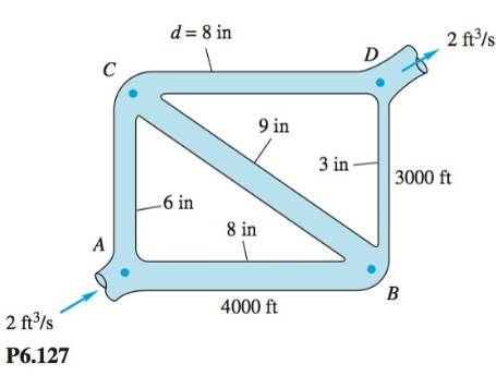
P6.128  Modify Prob. P6. 127 as follows: Let the inlet flow rate at A and the exit flow at D be unknown. Let
Expert Solution & Answer
Want to see the full answer?
Check out a sample textbook solution
Students have asked these similar questions
P.4.10
Oil of viscosity 10 mNs/m? and specific gravity 0.90, flows through 60 m of 100
mm diameter pipe and the pressure drop is 13.8 kN/m?. What will be the pressure drop
for a second oil of viscosity 30 mNs/m2 and specific gravity 0.95 flowing at the same
rate through the pipe? Assume the pipe wall to be smooth.
Ans.1.94x104 N/m?
2. Suppose the pump of Fig. P14-23 is operating at efficient condition. The pipe diameter after the pump is
"X" cm and pipe diameter before the pump is "Y" diameter. The friction losses along the pipe are negligible
(no need to use Darcy Equation). But there are minor losses in the system. They are as follows; the sharp
inlet is 0.50 m of water, each valve has a loss of 2.4 m of water, and each of the three elbows has a loss of
0.90 m of water. The contraction at the exit reduces the diameter by a factor of 0.60 (60% of the pipe
diameter(after the pump)), and the loss of the contraction is 0.15 m of water. The volume flow rate is "K"
Lpm. Density= 990kg/m. dynamic viscosity=1.002 x10³ kg/m-s. Z1-Z2="L". The kinetic energy correction
factor is 1. Determine (a) Required Head, (b) Required pump power (water Hp), (c) Reynolds number at
the exit.
V = 0
Reservoir
Pump
Given for Problem 2
X
Y
K
L
1.8
148
6
Water is flowing in a 5 cm diameter pipe at a velocity of 5 m/s. The pipe expands to a 10 cm diameter pipe. Calculate the pressure just after the expansion to a 10 cm diameter pipe if the prrssure in the 5 cm diameter pipe is 300 kPa. Friction is negligible. The specific weight of water is 9.81 kN/m³.A. 301.5 kPaB. 314.9 kPaC. 311.7 kPaD. 317.4 kPa
Chapter 6 Solutions
Fluid Mechanics
Ch. 6 - Prob. 6.1PCh. 6 - The present pumping rate of crude oil through the...Ch. 6 - The Keystone Pipeline in the chapter opener photo...Ch. 6 - For flow of SAE 30 oil through a 5-cm-diameter...Ch. 6 - In flow past a body or wall, early transition to...Ch. 6 - P6.6 For flow of a uniform stream parallel to a...Ch. 6 - SAE 10W30 oil at 20°C flows from a tank into a...Ch. 6 - P6.8 When water at 20°C is in steady turbulent...Ch. 6 - A light liquid 950kg/m3 flows at an average...Ch. 6 - Water at 20°C flows through an inclined...
Ch. 6 - Water at 20°C flows upward at 4 m/s in a...Ch. 6 - Prob. 6.12PCh. 6 - Prob. 6.13PCh. 6 - Prob. 6.14PCh. 6 - Prob. 6.15PCh. 6 - Prob. 6.16PCh. 6 - P6.17 A capillary viscometer measures the time...Ch. 6 - P6.18 SAE 50W oil at 20°C flows from one tank to...Ch. 6 - Prob. 6.19PCh. 6 - The oil tanks in Tinyland are only 160 cm high,...Ch. 6 - Prob. 6.21PCh. 6 - Prob. 6.22PCh. 6 - Prob. 6.23PCh. 6 - Prob. 6.24PCh. 6 - Prob. 6.25PCh. 6 - Prob. 6.26PCh. 6 - Let us attack Prob. P6.25 in symbolic fashion,...Ch. 6 - Prob. 6.28PCh. 6 - Prob. 6.29PCh. 6 - Prob. 6.30PCh. 6 - A laminar flow element (LFE) (Meriam Instrument...Ch. 6 - SAE 30 oil at 20°C flows in the 3-cm.diametcr pipe...Ch. 6 - Prob. 6.33PCh. 6 - Prob. 6.34PCh. 6 - In the overlap layer of Fig. 6.9a, turbulent shear...Ch. 6 - Prob. 6.36PCh. 6 - Prob. 6.37PCh. 6 - Prob. 6.38PCh. 6 - Prob. 6.39PCh. 6 - Prob. 6.40PCh. 6 - P6.41 Two reservoirs, which differ in surface...Ch. 6 - Prob. 6.42PCh. 6 - Prob. 6.43PCh. 6 - P6.44 Mercury at 20°C flows through 4 m of...Ch. 6 - P6.45 Oil, SG = 0.88 and v = 4 E-5 m2/s, flows at...Ch. 6 - Prob. 6.46PCh. 6 - Prob. 6.47PCh. 6 - Prob. 6.48PCh. 6 - Prob. 6.49PCh. 6 - Prob. 6.50PCh. 6 - Prob. 6.51PCh. 6 - Prob. 6.52PCh. 6 - Water at 2OC flows by gravity through a smooth...Ch. 6 - A swimming pool W by Y by h deep is to be emptied...Ch. 6 - Prob. 6.55PCh. 6 - Prob. 6.56PCh. 6 - Prob. 6.57PCh. 6 - Prob. 6.58PCh. 6 - P6.59 The following data were obtained for flow of...Ch. 6 - Prob. 6.60PCh. 6 - Prob. 6.61PCh. 6 - Water at 20°C is to be pumped through 2000 ft of...Ch. 6 - Prob. 6.63PCh. 6 - Prob. 6.64PCh. 6 - Prob. 6.65PCh. 6 - Prob. 6.66PCh. 6 - Prob. 6.67PCh. 6 - Prob. 6.68PCh. 6 - P6.69 For Prob. P6.62 suppose the only pump...Ch. 6 - Prob. 6.70PCh. 6 - Prob. 6.71PCh. 6 - Prob. 6.72PCh. 6 - Prob. 6.73PCh. 6 - Prob. 6.74PCh. 6 - Prob. 6.75PCh. 6 - P6.76 The small turbine in Fig. P6.76 extracts 400...Ch. 6 - Prob. 6.77PCh. 6 - Prob. 6.78PCh. 6 - Prob. 6.79PCh. 6 - The head-versus-flow-rate characteristics of a...Ch. 6 - Prob. 6.81PCh. 6 - Prob. 6.82PCh. 6 - Prob. 6.83PCh. 6 - Prob. 6.84PCh. 6 - Prob. 6.85PCh. 6 - SAE 10 oil at 20°C flows at an average velocity of...Ch. 6 - A commercial steel annulus 40 ft long, with a = 1...Ch. 6 - Prob. 6.88PCh. 6 - Prob. 6.89PCh. 6 - Prob. 6.90PCh. 6 - Prob. 6.91PCh. 6 - Prob. 6.92PCh. 6 - Prob. 6.93PCh. 6 - Prob. 6.94PCh. 6 - Prob. 6.95PCh. 6 - Prob. 6.96PCh. 6 - Prob. 6.97PCh. 6 - Prob. 6.98PCh. 6 - Prob. 6.99PCh. 6 - Prob. 6.100PCh. 6 - Prob. 6.101PCh. 6 - *P6.102 A 70 percent efficient pump delivers water...Ch. 6 - Prob. 6.103PCh. 6 - Prob. 6.104PCh. 6 - Prob. 6.105PCh. 6 - Prob. 6.106PCh. 6 - Prob. 6.107PCh. 6 - P6.108 The water pump in Fig. P6.108 maintains a...Ch. 6 - In Fig. P6.109 there are 125 ft of 2-in pipe, 75...Ch. 6 - In Fig. P6.110 the pipe entrance is sharp-edged....Ch. 6 - For the parallel-pipe system of Fig. P6.111, each...Ch. 6 - Prob. 6.112PCh. 6 - Prob. 6.113PCh. 6 - Prob. 6.114PCh. 6 - Prob. 6.115PCh. 6 - Prob. 6.116PCh. 6 - Prob. 6.117PCh. 6 - Prob. 6.118PCh. 6 - Prob. 6.119PCh. 6 - Prob. 6.120PCh. 6 - Prob. 6.121PCh. 6 - Prob. 6.122PCh. 6 - Prob. 6.123PCh. 6 - Prob. 6.124PCh. 6 - Prob. 6.125PCh. 6 - Prob. 6.126PCh. 6 - Prob. 6.127PCh. 6 - In the five-pipe horizontal network of Fig....Ch. 6 - Prob. 6.129PCh. 6 - Prob. 6.130PCh. 6 - Prob. 6.131PCh. 6 - Prob. 6.132PCh. 6 - Prob. 6.133PCh. 6 - Prob. 6.134PCh. 6 - An airplane uses a pitot-static tube as a...Ch. 6 - Prob. 6.136PCh. 6 - Prob. 6.137PCh. 6 - Prob. 6.138PCh. 6 - P6.139 Professor Walter Tunnel needs to measure...Ch. 6 - Prob. 6.140PCh. 6 - Prob. 6.141PCh. 6 - Prob. 6.142PCh. 6 - Prob. 6.143PCh. 6 - Prob. 6.144PCh. 6 - Prob. 6.145PCh. 6 - Prob. 6.146PCh. 6 - Prob. 6.147PCh. 6 - Prob. 6.148PCh. 6 - Prob. 6.149PCh. 6 - Prob. 6.150PCh. 6 - Prob. 6.151PCh. 6 - Prob. 6.152PCh. 6 - Prob. 6.153PCh. 6 - Prob. 6.154PCh. 6 - Prob. 6.155PCh. 6 - Prob. 6.156PCh. 6 - Prob. 6.157PCh. 6 - Prob. 6.158PCh. 6 - Prob. 6.159PCh. 6 - Prob. 6.160PCh. 6 - Prob. 6.161PCh. 6 - Prob. 6.162PCh. 6 - Prob. 6.163PCh. 6 - Prob. 6.1WPCh. 6 - Prob. 6.2WPCh. 6 - Prob. 6.3WPCh. 6 - Prob. 6.4WPCh. 6 - Prob. 6.1FEEPCh. 6 - Prob. 6.2FEEPCh. 6 - Prob. 6.3FEEPCh. 6 - Prob. 6.4FEEPCh. 6 - Prob. 6.5FEEPCh. 6 - Prob. 6.6FEEPCh. 6 - Prob. 6.7FEEPCh. 6 - Prob. 6.8FEEPCh. 6 - Prob. 6.9FEEPCh. 6 - Prob. 6.10FEEPCh. 6 - Prob. 6.11FEEPCh. 6 - Prob. 6.12FEEPCh. 6 - Prob. 6.13FEEPCh. 6 - Prob. 6.14FEEPCh. 6 - Prob. 6.15FEEPCh. 6 - Prob. 6.1CPCh. 6 - Prob. 6.2CPCh. 6 - Prob. 6.3CPCh. 6 - Prob. 6.4CPCh. 6 - Prob. 6.5CPCh. 6 - Prob. 6.6CPCh. 6 - Prob. 6.7CPCh. 6 - Prob. 6.8CPCh. 6 - Prob. 6.9CPCh. 6 - A hydroponic garden uses the 10-m-long...Ch. 6 - It is desired to design a pump-piping system to...
Knowledge Booster


Learn more about
Need a deep-dive on the concept behind this application? Look no further. Learn more about this topic, mechanical-engineering and related others by exploring similar questions and additional content below.Similar questions
- Q.5 A pump circulates water through a closed pipe network connecting a water heater and a heating coil (heat exchanger) in a room. The total length of the pipe is 28 m and the diameter is 32 mm. There are six 90°-elbows and a globe valve in the network. The head loss through the water heater and the heating coil are 1.6 m and 1.2 m respectively. The water flow rate is 0.88 Ls!. The system uses schedule-40 steel pipes with threaded fittings. Calculate the (i) flow velocity and the unit pressure loss in the pipe. (ii) increase in head across the pump. (iii) power input to the pump if the efficiency of the pump is 70%.arrow_forwardFor a flow of oil (m = 0.1 N.s/m´, S.G. = 0.28 ) %3D %3D through a horizontal, straight, smooth 5 cm 3 diameter pipe at 14 m /hr, the Reynolds number for 10 m long pipe is approximately: Select one: a. 221.28316 b. 193.28316 c. 165.28316 d. 249.28316 e. 277.28316arrow_forwardQ.2 A centrifugal pump is required to pump water to an open water tank situated 4 km away from the location of the pump through a pipe f diameter 0.2 m having Darcy's frřiction factor of 0.01. The average speed of waterinthe pipe is 2 m/s. If it is to maintain a constant heac of 5 m in the tank, neglecting other minor losses, the absolute discharge pressure at the pump exit is (a) 0.449 bar (c) 44.911 bar dund (b) 5.503 bar (d) 55.203 bararrow_forward
- HAH 5.6.4. Consider a pump-pipeline system that delivers water from a reservoir A to B with the elevations EA = 45.5 m and EB = 52.9 m. The pipe has a length L = 3,050 m, diameter D = 0.50 m, and Darcy-Weisbach friction factor f = 0.02. Minor losses include an inlet, Kin = 0.5, exit Kexit = 1.0, and a swing-type check valve (see Table 8.2). The pump characteristics are shown in the following table. Q (m³/s) ho (m) 0.00 0.15 89.8 91.4 b. C. 0.30 0.45 0.60 85.1 77.2 65.9 0.75 52.6 0.90 1.05 15.7 36.3 a. Verify graphically that when a single pump is used in the pipeline, the flow rate is Q = 0.595 m³/s with a pump head of approximately h₁ = 66.3 m. Determine the flow rate if two identical pumps are used in series. Determine the flow rate if two identical pumps are used in parallel.arrow_forwardQn.2. A piezometer and a Pitot tube are tapped into a horizontal water pipe, as shown in the Figure I below to measure static and stagnation (static + dynamic) pressures. For the indicated water column heights, determine the velocity at the center of the pipe. Clearly state all asuumptions and illustrations. hy-12 cm h- 7 cm hy-3 cm Water Stagnation point Figure 1arrow_forwardKindly answer all. I know as per bartleby first three parts solved.... Please please kindly help me with all answers. A. Demonstrate the application / Use of Moody’s chart in the solution of Steady Incompressible Flow in Pressure Conduits. B. Demonstrate shortly difference between type 1, type2, and type3 pipe flow solutions. C. Differentiate between centrifugal and reciprocating pumps. D. Quantify (derive) the force exerted by jet in the direction of flow impinging on inclined fixed plate?arrow_forward
- 1. Water flows through a pipe at a velocity of 3.25 m/s. What is the velocity head? A. 0.632 mB. 0.538 mC. 0.281 mD. 1.394 m 2. A submarine fitted with a pilot tube moves horizontally in sea. The pitot tube fixed in front of the submarine and along its axis is connected to the two limbs of a U-tube containing mercury, the reading of which is found to be 200mm. Find the speed of the submarine in m/s A. 7.31B. 6.48C. 6.94D. 7.20arrow_forwardAn anaerobic digester (sealed, ID: 20 m) is used to produce renewable fuel from agricultural biomass. The head space pressure is maintained at 18.6 psi. A commercial steel pipe (20 cm) is connected to the bottom of the digester to remove the biofuel (y= 2000 N/m³, vapor pressure 0.2 psi) generated at 0.034 m³/s. A centrifugal pump (Taco® Model 4007, 7.00 in, operated at 1760 rpm) will be used. Assuming the head loss in the pipe is 225 ft, which of the following elevation can the pump be located? HEAD IN FEET 75 60 45 OO 15 Taco® L/SEC 5 0 7.50"(191mm) 6.00" (152mm). T I 30 5.50"(140mm) 0 7.00"(178mm) 6.50"(165mm) 10 O Both of these CURVES BASED ON CLEAR WATER WITH SPECIFIC GRAVITY OF 1.0 O Neither of these 15 125 Model 4007 FI & CI Series 20 25 O 30 ft below the liquid surface in the digester O 15 ft below the liquid surface in the digester 30 208 1760 RPM November 1, 2010 40 45 (2.2KW) 3HP 35 REQUIRED NPSH -82%1 80% LL 75%. 5HP (3 7KW) 250 375 500 625 FLOW IN GALLONS PER MINUTE Curve…arrow_forwardThe following are general features of Spring & Diaphragm EXCEPT А. Simple mechanism В. Cost effective C. Based on air pressure Require electric supply D.arrow_forward
- Shown below is an inverted U-tube which is used to drain alcohol from a tank reservoir. The bend of the inverted tube is 1 meter above the free surface of the alcohol in the tank and 10.5 meters above the ground where the alcohol is discharged. Alcohol exits the tube at atmospheric pressure. The Specific gravity of alcohol is 0.89 while g= 9.81. The pressure, in kilopascal, in the bend is Blank 1 P=? ... 1 m ..... ...arrow_forwardThe pump-turbine system in the Figure draws water from the upper reservoir in the daytime to produce power for a city. At night, it pumps water from lower to upper reservoirs to restore the situation. For a design flow rate of 15,000 gal/min in either direction, the friction head loss is 17 ft. Estimate the power in kW: (a) extracted by the turbine and (b) delivered by the 1- Select coordinates and points 1 and 2 2- Write down your assumptions 3- Apply Energy Eq. and start finding P, V, and z for points 1 and 2 as well as head (h) values 4- Solve for unknown (1) Z₁ = 150 ft pump. Water at 20°C Pump- turbine (2) 2 Z₂ = 25 ft P1 V² + pg 2g P2 V + +Z2+hfriction + hTurbine - hpump [pressure head] 29 +Z1 = pgarrow_forwardA venturi meter, shown in Fig. designed constriction whose pressure difference is a mea- sure of the flow rate in a pipe. Using Bernoulli's equation for steady incompressible flow with no losses, show that the flow rate Q is related to the manometer reading h by is a carefully 2gh(PM – p). A2 VT- (D/D;)4 where py is the density of the manometer fluid. 2arrow_forward
arrow_back_ios
SEE MORE QUESTIONS
arrow_forward_ios
Recommended textbooks for you
 Elements Of ElectromagneticsMechanical EngineeringISBN:9780190698614Author:Sadiku, Matthew N. O.Publisher:Oxford University Press
 Mechanics of Materials (10th Edition)Mechanical EngineeringISBN:9780134319650Author:Russell C. HibbelerPublisher:PEARSON
 Thermodynamics: An Engineering ApproachMechanical EngineeringISBN:9781259822674Author:Yunus A. Cengel Dr., Michael A. BolesPublisher:McGraw-Hill Education
 Control Systems EngineeringMechanical EngineeringISBN:9781118170519Author:Norman S. NisePublisher:WILEY
 Mechanics of Materials (MindTap Course List)Mechanical EngineeringISBN:9781337093347Author:Barry J. Goodno, James M. GerePublisher:Cengage Learning
 Engineering Mechanics: StaticsMechanical EngineeringISBN:9781118807330Author:James L. Meriam, L. G. Kraige, J. N. BoltonPublisher:WILEY
Elements Of Electromagnetics
Mechanical Engineering
ISBN:9780190698614
Author:Sadiku, Matthew N. O.
Publisher:Oxford University Press
Mechanics of Materials (10th Edition)
Mechanical Engineering
ISBN:9780134319650
Author:Russell C. Hibbeler
Publisher:PEARSON
Thermodynamics: An Engineering Approach
Mechanical Engineering
ISBN:9781259822674
Author:Yunus A. Cengel Dr., Michael A. Boles
Publisher:McGraw-Hill Education
Control Systems Engineering
Mechanical Engineering
ISBN:9781118170519
Author:Norman S. Nise
Publisher:WILEY
Mechanics of Materials (MindTap Course List)
Mechanical Engineering
ISBN:9781337093347
Author:Barry J. Goodno, James M. Gere
Publisher:Cengage Learning
Engineering Mechanics: Statics
Mechanical Engineering
ISBN:9781118807330
Author:James L. Meriam, L. G. Kraige, J. N. Bolton
Publisher:WILEY
Fluid Mechanics - Viscosity and Shear Strain Rate in 9 Minutes!; Author: Less Boring Lectures;https://www.youtube.com/watch?v=_0aaRDAdPTY;License: Standard youtube license