
PEARSON ETEXT ENGINEERING MECH & STATS
15th Edition
ISBN: 9780137514724
Author: HIBBELER
Publisher: PEARSON
expand_more
expand_more
format_list_bulleted
Concept explainers
Videos
Textbook Question
Chapter 6, Problem 15FP
If a 100-N force is applied to the handles of the pliers, determine the clamping force exerted on the smooth pipe B and the magnitude of the resultant force that one of the members exerts on pin A.
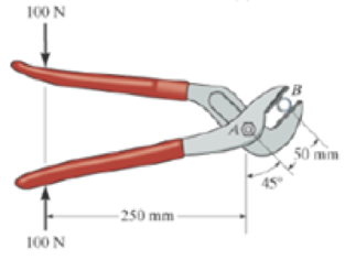
Prob. F6-15
Expert Solution & Answer
Want to see the full answer?
Check out a sample textbook solution
Students have asked these similar questions
Determine the n- and t-components of the force F which is exerted by the rod AB on the crank OA. Evaluate your general expression for F = 106 N and (a) e = 16°, B = 14° and (b) e = 23°, B = 30°
B
Answers:
N, F =|
N
(a) Fn =
N
(b) Fo
N, F =
Determine the n- and t-components of the force F which is exerted by the rod AB on the crank OA. Evaluate your general expression
for F-119 N and (a) 0-24°, B-16° and (b) 0-24°, B-29⁰
Answers:
(a) F-
i
N, F.-
i
N
(b) Fi
N. F
i
N
Determine the n- and t-components of the force F which is exerted by the rod AB on the crank OA. Evaluate your general expression
for F = 90 N and (a) 0 = 29°, 3= 25° and (b) = 14°, 3 = 37°
Answers:
(a) Fn =
(b) Fn =
i
i
B
BI
A
N, Ft=
N, Ft=
i
N
N
Chapter 6 Solutions
PEARSON ETEXT ENGINEERING MECH & STATS
Ch. 6 - Determine the force in each member of the truss....Ch. 6 - Determine the force in each member of the truss....Ch. 6 - Determine the force in each member of the truss....Ch. 6 - Determine the greatest load P that can be applied...Ch. 6 - Identify the zero-force members in the truss....Ch. 6 - Determine the force in each member of the truss....Ch. 6 - Determine the force in each member of the truss...Ch. 6 - Determine the force in each member of the truss...Ch. 6 - Determine the force in each member of the truss...Ch. 6 - Determine the force in each member of the truss in...
Ch. 6 - Members AB and BC can each support a maximum...Ch. 6 - Members AB and BC can each support a maximum...Ch. 6 - Determine the force in each member of the truss....Ch. 6 - If the maximum force that any member can support...Ch. 6 - Determine the force in each member of the truss...Ch. 6 - Determine the force in each member of the truss...Ch. 6 - Prob. 22PCh. 6 - Determine the force in members BC, CF, and FE....Ch. 6 - Determine the force in members LK, KC, and CD of...Ch. 6 - Determine the force in members KJ, KD, and CD of...Ch. 6 - Determine the force in members EF, CF, and BC of...Ch. 6 - Determine the force in members DC, HC, and HI of...Ch. 6 - Determine the force in members ED, EH, and GH of...Ch. 6 - Determine the force in members HG, HE and DE of...Ch. 6 - Determine the force in members CD, HI, and CH of...Ch. 6 - Prob. 39PCh. 6 - Determine the force in members CD, CF, and CG and...Ch. 6 - Determine the force developed in members FE, EB,...Ch. 6 - Determine the force in members CD, CJ, GJ, and CG...Ch. 6 - Prob. 48PCh. 6 - Determine the force in members HI, FI, and EF of...Ch. 6 - Determine the force P needed to hold the 60-lb...Ch. 6 - Determine the horizontal and vertical components...Ch. 6 - If a 100-N force is applied to the handles of the...Ch. 6 - Determine the normal force that the 100-lb plate A...Ch. 6 - Determine the force P needed to lift the load....Ch. 6 - Prob. 19FPCh. 6 - Prob. 20FPCh. 6 - Determine the components of reaction at A and C....Ch. 6 - Determine the components of reaction at C. Prob....Ch. 6 - Determine the components of reaction at E. Prob....Ch. 6 - Determine the components of reaction at D and the...Ch. 6 - Determine the force P required to hold the 100-lb...Ch. 6 - Determine the horizontal and vertical components...Ch. 6 - The bridge frame consists of three segments which...Ch. 6 - Determine the reactions at supports A and B. Prob....Ch. 6 - Determine the horizontal and vertical components...Ch. 6 - The compound beam is pin supported at B and...Ch. 6 - When a force of 2 lb is applied to the handles of...Ch. 6 - The hoist supports the 125-kg engine. Determine...Ch. 6 - Prob. 88PCh. 6 - Determine the horizontal and vertical components...Ch. 6 - The pipe cutter is clamped around the pipe P. If...Ch. 6 - Five coins are stacked in the smooth plastic...Ch. 6 - The nail cutter consists of the handle and the two...Ch. 6 - A man having a weight of 175 lb attempts to hold...Ch. 6 - Prob. 97PCh. 6 - If a force of F = 350 N is applied to the handle...Ch. 6 - Prob. 106PCh. 6 - If a force of F = 50 lb is applied to the pads at...Ch. 6 - The spring has an unstretched length of 0.3 m....Ch. 6 - The spring has an unstretched length of 0.3 m....Ch. 6 - The piston C moves vertically between the two...Ch. 6 - Prob. 113PCh. 6 - The platform scale consists of a combination of...Ch. 6 - The three pin-connected members shown in the top...Ch. 6 - Determine the force in each member of the truss...Ch. 6 - Determine the force in each member of the truss...Ch. 6 - Determine the force in member GJ and GC of the...Ch. 6 - Determine the force in members GF, FB, and BC of...Ch. 6 - Determine the horizontal and vertical components...Ch. 6 - Determine the horizontal and vertical components...Ch. 6 - Determine the resultant forces at pins B and C on...
Knowledge Booster


Learn more about
Need a deep-dive on the concept behind this application? Look no further. Learn more about this topic, mechanical-engineering and related others by exploring similar questions and additional content below.Similar questions
- 6-85. The three power lines exert the forces shown on the truss joints, which in turn are pin-connected to the poles AH and EG. Determine the force in the guy cable AI and the pin reaction at the support H. 20 ft D B -40 ft--40 ft- 800 lb 800 lb H 800 lb -50 ft-30 ft--30 20 ft -30 ft-30 ft-30 ft-30 ft 30 ft-30 20 ft ft-50 ft- 125 ftarrow_forwardDetermine the n- and t-components of the force F which is exerted by the rod AB on the crank OA. Evaluate your general expression for F-101 N and (a) = 29°, -21° and (b) 0 -25°, 3 - 36° B Answers: (a) F= N (b) Fn- N i i N, F₂ i N. F iarrow_forward6-127. Determine the clamping force exerted on the smooth pipe at B if a force of 20 lb is applied to the handles of the pliers. The pliers are pinned together at A. 20 lb 20 lb 10 in. 40° 1.5 in. 0.5 in. Barrow_forward
- 3-2. The members of a truss are pin connected at joint O. Determine the magnitude of F, and its angle for equilibrium. Set F - 6 KN. 5 kN 70 30 7 KN Probs. 3-1/2arrow_forwardDetermine the resultant force at pins A, B, and C on the three-member frame. Given: F = 40N, w = 10, L = 1.arrow_forward6-34. Determine the force in members JK, CJ, and CD of the truss, and state if the members are in tension or compression. Determine the force in members HI, FI, and EF of the truss, and state if the members are in tension or compression. K 3 m Is G E F |-2 m--2 m--2 m-|-2 m--2 m--2 m-| B |C |D 4 kN 5 kN 8 kN 6 kN Probs. 6-34/35 Answers FK =11.111KN = 11.1 kN (C) FCD = 12 kN (T) Fc =1.602 kN = 1.60 kN (C)arrow_forward
- R3-5. The joint of a space frame is subjected to four member forces. Member OA lies in the x-y plane and member OB lies in the y-z plane. Determine the force acting in each of the members required for equilibrium of the joint. Fs 200 N Prob. R3-5 Barrow_forward30°- 50 mm -20 mm- 10 mm The operation of the fuel pump for an automobile depends on the reciprocating action of the rocker arm ABC, which is pinned at B and is spring loaded at A and D. The vertical force acting on the rocker arm at A is FA = 50N, and at C it is Fc = 150N. When the smooth cam C is in the position shown, determine the magnitude of the force at B wwwwarrow_forward6-50. Determine the force in each member of the truss and state if the members are in tension or compression. Set P = 20 kN, P, = 10 kN. Determine the force in each member of the truss and state if the members are in tension or compression. Set P, = 40 kN, P2 = 20 kN. B C D 2 m E A |F -1.5 m--1.5 m--1.5 m-|-1.5 m-| |G P2 Probs. 6–50/51 Answers: FA = 21.875 = 21.9 kN (C) ; Fag = 13.125 = 13.1 kN (T)arrow_forward
- *3-12. The concrete pipe elbow has a weight of 400 lb and the center of gravity is located at point G. Determine the force FAR and the tension in cables BC and BD needed to support it. FAB B 30 in, 45° 45° 30 in. D Garrow_forwardThe cable AB prevents bar OA from rotating clockwise about the pivot O. If the cable tension is 820 N, determine the n- and t- components of this force acting on point A of the bar. 2.0 m B Answers: Tn= i Tt= i Attempts: 0 of 4 used Submit Answer -1.5 m Save for Later 63⁰ Z Z N Narrow_forward3/3 The weight of the bicycle is 29 lb with center of grav- ity at G. Determine the normal forces at A and B when the bicycle is in equilibrium. B - 22.5"- -18.5"- Problem 3/3arrow_forward
arrow_back_ios
SEE MORE QUESTIONS
arrow_forward_ios
Recommended textbooks for you
 Elements Of ElectromagneticsMechanical EngineeringISBN:9780190698614Author:Sadiku, Matthew N. O.Publisher:Oxford University Press
 Mechanics of Materials (10th Edition)Mechanical EngineeringISBN:9780134319650Author:Russell C. HibbelerPublisher:PEARSON
 Thermodynamics: An Engineering ApproachMechanical EngineeringISBN:9781259822674Author:Yunus A. Cengel Dr., Michael A. BolesPublisher:McGraw-Hill Education
 Control Systems EngineeringMechanical EngineeringISBN:9781118170519Author:Norman S. NisePublisher:WILEY
 Mechanics of Materials (MindTap Course List)Mechanical EngineeringISBN:9781337093347Author:Barry J. Goodno, James M. GerePublisher:Cengage Learning
 Engineering Mechanics: StaticsMechanical EngineeringISBN:9781118807330Author:James L. Meriam, L. G. Kraige, J. N. BoltonPublisher:WILEY
Elements Of Electromagnetics
Mechanical Engineering
ISBN:9780190698614
Author:Sadiku, Matthew N. O.
Publisher:Oxford University Press
Mechanics of Materials (10th Edition)
Mechanical Engineering
ISBN:9780134319650
Author:Russell C. Hibbeler
Publisher:PEARSON
Thermodynamics: An Engineering Approach
Mechanical Engineering
ISBN:9781259822674
Author:Yunus A. Cengel Dr., Michael A. Boles
Publisher:McGraw-Hill Education
Control Systems Engineering
Mechanical Engineering
ISBN:9781118170519
Author:Norman S. Nise
Publisher:WILEY
Mechanics of Materials (MindTap Course List)
Mechanical Engineering
ISBN:9781337093347
Author:Barry J. Goodno, James M. Gere
Publisher:Cengage Learning
Engineering Mechanics: Statics
Mechanical Engineering
ISBN:9781118807330
Author:James L. Meriam, L. G. Kraige, J. N. Bolton
Publisher:WILEY
How to Measure Threads; Author: PracticalMachinist;https://www.youtube.com/watch?v=Uuy7EViS7Kc;License: Standard Youtube License