
PEARSON ETEXT ENGINEERING MECH & STATS
15th Edition
ISBN: 9780137514724
Author: HIBBELER
Publisher: PEARSON
expand_more
expand_more
format_list_bulleted
Concept explainers
Videos
Textbook Question
Chapter 6, Problem 102P
If a force of F = 350 N is applied to the handle of the toggle clamp, determine the resulting clamping force at A.
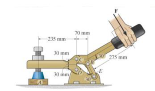
Prob. 6-102
Expert Solution & Answer
Want to see the full answer?
Check out a sample textbook solution
Students have asked these similar questions
*4-12. The rigid metal strip of negligible weight is used as
part of an electromagnetic switch. If the stiffness of the
springs at A and B is k -5 N/m and the strip is originally
horizontal when the springs are unstretched, determine the
smallest force Fneeded to close the contact gap at C.
-50 mm
-50 mm
10 mm
5-50. The machine shown is used for forming metal plates. It
consists of two toggles ABC and DEF, which are operated by
the hydraulic cylinder H. The toggles push the movable bar G
forward, pressing the plate p into the cavity. If the force which
the plate exerts on the head is P - 12 kN, determine the
force Fin the hydraulic cylinder when 8 - 30.
e = 30
200 mm
00 mm
P= 12 kN
-F
200 mm
200 mm
= 30
4-69. The pipe assembly is secured on the wall by the two brackets. If the frictional force of
both brackets can resist a maximum moment of 150 lb-ft, determine the largest weight of the
flowerpot that can be supported by the assembly.
Problems 4-68/69
O
2
60°
4 ft
4 ft
3 ft
30°
3 ft
B
Chapter 6 Solutions
PEARSON ETEXT ENGINEERING MECH & STATS
Ch. 6 - Determine the force in each member of the truss....Ch. 6 - Determine the force in each member of the truss....Ch. 6 - Determine the force in each member of the truss....Ch. 6 - Determine the greatest load P that can be applied...Ch. 6 - Identify the zero-force members in the truss....Ch. 6 - Determine the force in each member of the truss....Ch. 6 - Determine the force in each member of the truss...Ch. 6 - Determine the force in each member of the truss...Ch. 6 - Determine the force in each member of the truss...Ch. 6 - Determine the force in each member of the truss in...
Ch. 6 - Members AB and BC can each support a maximum...Ch. 6 - Members AB and BC can each support a maximum...Ch. 6 - Determine the force in each member of the truss....Ch. 6 - If the maximum force that any member can support...Ch. 6 - Determine the force in each member of the truss...Ch. 6 - Determine the force in each member of the truss...Ch. 6 - Prob. 22PCh. 6 - Determine the force in members BC, CF, and FE....Ch. 6 - Determine the force in members LK, KC, and CD of...Ch. 6 - Determine the force in members KJ, KD, and CD of...Ch. 6 - Determine the force in members EF, CF, and BC of...Ch. 6 - Determine the force in members DC, HC, and HI of...Ch. 6 - Determine the force in members ED, EH, and GH of...Ch. 6 - Determine the force in members HG, HE and DE of...Ch. 6 - Determine the force in members CD, HI, and CH of...Ch. 6 - Prob. 39PCh. 6 - Determine the force in members CD, CF, and CG and...Ch. 6 - Determine the force developed in members FE, EB,...Ch. 6 - Determine the force in members CD, CJ, GJ, and CG...Ch. 6 - Prob. 48PCh. 6 - Determine the force in members HI, FI, and EF of...Ch. 6 - Determine the force P needed to hold the 60-lb...Ch. 6 - Determine the horizontal and vertical components...Ch. 6 - If a 100-N force is applied to the handles of the...Ch. 6 - Determine the normal force that the 100-lb plate A...Ch. 6 - Determine the force P needed to lift the load....Ch. 6 - Prob. 19FPCh. 6 - Prob. 20FPCh. 6 - Determine the components of reaction at A and C....Ch. 6 - Determine the components of reaction at C. Prob....Ch. 6 - Determine the components of reaction at E. Prob....Ch. 6 - Determine the components of reaction at D and the...Ch. 6 - Determine the force P required to hold the 100-lb...Ch. 6 - Determine the horizontal and vertical components...Ch. 6 - The bridge frame consists of three segments which...Ch. 6 - Determine the reactions at supports A and B. Prob....Ch. 6 - Determine the horizontal and vertical components...Ch. 6 - The compound beam is pin supported at B and...Ch. 6 - When a force of 2 lb is applied to the handles of...Ch. 6 - The hoist supports the 125-kg engine. Determine...Ch. 6 - Prob. 88PCh. 6 - Determine the horizontal and vertical components...Ch. 6 - The pipe cutter is clamped around the pipe P. If...Ch. 6 - Five coins are stacked in the smooth plastic...Ch. 6 - The nail cutter consists of the handle and the two...Ch. 6 - A man having a weight of 175 lb attempts to hold...Ch. 6 - Prob. 97PCh. 6 - If a force of F = 350 N is applied to the handle...Ch. 6 - Prob. 106PCh. 6 - If a force of F = 50 lb is applied to the pads at...Ch. 6 - The spring has an unstretched length of 0.3 m....Ch. 6 - The spring has an unstretched length of 0.3 m....Ch. 6 - The piston C moves vertically between the two...Ch. 6 - Prob. 113PCh. 6 - The platform scale consists of a combination of...Ch. 6 - The three pin-connected members shown in the top...Ch. 6 - Determine the force in each member of the truss...Ch. 6 - Determine the force in each member of the truss...Ch. 6 - Determine the force in member GJ and GC of the...Ch. 6 - Determine the force in members GF, FB, and BC of...Ch. 6 - Determine the horizontal and vertical components...Ch. 6 - Determine the horizontal and vertical components...Ch. 6 - Determine the resultant forces at pins B and C on...
Knowledge Booster


Learn more about
Need a deep-dive on the concept behind this application? Look no further. Learn more about this topic, mechanical-engineering and related others by exploring similar questions and additional content below.Similar questions
- 6-65 Determine the horizontal and vertical components of force that pins A and B exert on the frame. C is a pinned connection. A and B are pinned supports. 4 m A -3 m- C 2 kN/m Barrow_forward6-85. The three power lines exert the forces shown on the truss joints, which in turn are pin-connected to the poles AH and EG. Determine the force in the guy cable AI and the pin reaction at the support H. 20 ft D B -40 ft--40 ft- 800 lb 800 lb H 800 lb -50 ft-30 ft--30 20 ft -30 ft-30 ft-30 ft-30 ft 30 ft-30 20 ft ft-50 ft- 125 ftarrow_forward6-127. Determine the clamping force exerted on the smooth pipe at B if a force of 20 lb is applied to the handles of the pliers. The pliers are pinned together at A. 20 lb 20 lb 10 in. 40° 1.5 in. 0.5 in. Barrow_forward
- If a force of F=350N is applied to the handle of the toggle clamp, determine the resulting clamping force at A.arrow_forward30°- 50 mm -20 mm- 10 mm The operation of the fuel pump for an automobile depends on the reciprocating action of the rocker arm ABC, which is pinned at B and is spring loaded at A and D. The vertical force acting on the rocker arm at A is FA = 50N, and at C it is Fc = 150N. When the smooth cam C is in the position shown, determine the magnitude of the force at B wwwwarrow_forward4-19. The assembly consists of two A-36 steel rods and a rigid bar BD. Each rod has a diameter of 0.75 in. If a force of 10 kip is applied to the bar, determine the angle of tilt of the bar. 3 ft 2 ft E D -1.25 ft- 0.75 ft 1 ft 10 kip END Thank youarrow_forward
- 4-19. The rigid metal strip of negligible weight is used as part of an electromagnetic switch. Determine the maximum stiffness k of the springs at A and B so that the contact at C closes when the vertical force developed there is F - 0.5 N. Originally the strip is horizontal as shown. -50 mm -50 mm- 10 mmarrow_forward*5-36. A 300-kg counterweight, with center of mass at G, is mounted on the pitman crank AB of the oil-pumping unit. If a force of F - 5 KN is to be developed in the fixed cable attached to the end of the walking beam DEF, determine the torque M that must be supplied by the motor. -1.75 m -2.50 m 30 05 m 0.65 marrow_forwardDetermine the magnitude of the vertical clamping force at E in terms of the force Papplied to the handle of the toggle clamp. 75 mm 160 mm- 15 mm 12 mm 13 mm 6 mm '12 mm Answer: E = Parrow_forward
- Determine the n- and t-components of the force F which is exerted by the rod AB on the crank OA. Evaluate your general expression for F-101 N and (a) = 29°, -21° and (b) 0 -25°, 3 - 36° B Answers: (a) F= N (b) Fn- N i i N, F₂ i N. F iarrow_forward5-50. The machine shown is used for forming metal plates. It consists of two toggles ABC and DEF, which are operated by the hydraulic cylinder H. The toggles push the movable bar G forward, pressing the plate p into the cavity. If the force which the plate exerts on the head is P = 12 kN, determine the force F in the hydraulic cylinder when 0 = 30°. U D 200 mm 200 mm A 0 = 30° E -F F H B 0 = 30° F 200 mm 200 mm C Prob. 5-50 G р ▬▬▬ P = 12 kN ▬▬arrow_forward3-45. The lug nut on the wheel of the automobile is to be removed using the wrench and applying the vertical force of F = 30 Nat A. Determine if this force is adequate, provided 14 N- m of torque about the x axis is initially required to turn the nut. If the 30-N force can be applied at A in any other direction, will it be possible to turn the nut? F = 30 N 0.25 m 03my 0.5 m 0.1 myarrow_forward
arrow_back_ios
SEE MORE QUESTIONS
arrow_forward_ios
Recommended textbooks for you
 Elements Of ElectromagneticsMechanical EngineeringISBN:9780190698614Author:Sadiku, Matthew N. O.Publisher:Oxford University Press
 Mechanics of Materials (10th Edition)Mechanical EngineeringISBN:9780134319650Author:Russell C. HibbelerPublisher:PEARSON
 Thermodynamics: An Engineering ApproachMechanical EngineeringISBN:9781259822674Author:Yunus A. Cengel Dr., Michael A. BolesPublisher:McGraw-Hill Education
 Control Systems EngineeringMechanical EngineeringISBN:9781118170519Author:Norman S. NisePublisher:WILEY
 Mechanics of Materials (MindTap Course List)Mechanical EngineeringISBN:9781337093347Author:Barry J. Goodno, James M. GerePublisher:Cengage Learning
 Engineering Mechanics: StaticsMechanical EngineeringISBN:9781118807330Author:James L. Meriam, L. G. Kraige, J. N. BoltonPublisher:WILEY
Elements Of Electromagnetics
Mechanical Engineering
ISBN:9780190698614
Author:Sadiku, Matthew N. O.
Publisher:Oxford University Press
Mechanics of Materials (10th Edition)
Mechanical Engineering
ISBN:9780134319650
Author:Russell C. Hibbeler
Publisher:PEARSON
Thermodynamics: An Engineering Approach
Mechanical Engineering
ISBN:9781259822674
Author:Yunus A. Cengel Dr., Michael A. Boles
Publisher:McGraw-Hill Education
Control Systems Engineering
Mechanical Engineering
ISBN:9781118170519
Author:Norman S. Nise
Publisher:WILEY
Mechanics of Materials (MindTap Course List)
Mechanical Engineering
ISBN:9781337093347
Author:Barry J. Goodno, James M. Gere
Publisher:Cengage Learning
Engineering Mechanics: Statics
Mechanical Engineering
ISBN:9781118807330
Author:James L. Meriam, L. G. Kraige, J. N. Bolton
Publisher:WILEY
EVERYTHING on Axial Loading Normal Stress in 10 MINUTES - Mechanics of Materials; Author: Less Boring Lectures;https://www.youtube.com/watch?v=jQ-fNqZWrNg;License: Standard YouTube License, CC-BY