
Statics and Mechanics of Materials (5th Edition)
5th Edition
ISBN: 9780134382593
Author: Russell C. Hibbeler
Publisher: PEARSON
expand_more
expand_more
format_list_bulleted
Videos
Textbook Question
Chapter 5.5, Problem 61P
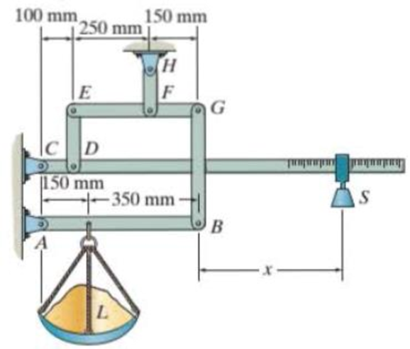
The platform scale consists of a combination of third and first class levers so that the load on one lever becomes the effort that moves the next lever. Through this arrangement a small weight can balance a massive object. If x = 450 mm, and the mass of the counterweight S is 2 kg, determine the mass of the load L required to maintain the balance.
Probs. 5-60/61
Expert Solution & Answer
Want to see the full answer?
Check out a sample textbook solution
Students have asked these similar questions
5-61. The platform scale consists of a combination of third
and first class levers so that the load on one lever becomes the
effort that moves the next lever. Through this arrangement, a
small weight can balance a massive object. If x-450 mm, and
the mass of the counterweight S is 2 kg, determine the mass of
the load L required to maintain the balance.
100 mm
250 mm 50 mm
Ic D
150 mm
-350 mm -
*5-60. The platform scale consists of a combination of third
and first class levers so that the load on one lever becomes the
effort that moves the next lever. Through this arrangement, a
small weight can balance a massive object. If x- 450 mm,
determine the required mass of the counterweight S required
to balance the load L having a mass of 90 kg.
100 mm.
250 mm 50 mm
Ic D
150 mm
-350 mm -
C4-1. Draw the free-body diagram of the uniform trash
bucket which has a significant weight. It is pinned at A and
rests aganist the smooth horizontal member at B. Show your
result in side view. Label any necessary dimensions.
Chapter 5 Solutions
Statics and Mechanics of Materials (5th Edition)
Ch. 5.3 - In each ease, calculate the support reactions and...Ch. 5.3 - Identify the zero-force members in each truss....Ch. 5.3 - Determine the force in each member of the truss...Ch. 5.3 - Determine the force in each member of the truss...Ch. 5.3 - Determine the force in each member of the truss...Ch. 5.3 - Determine the greatest load P that can be applied...Ch. 5.3 - Identify the zero-force members in the truss....Ch. 5.3 - Determine the force in each member of the truss...Ch. 5.3 - Determine the force in each member of the truss...Ch. 5.3 - Determine the force in each member of the truss...
Ch. 5.3 - Determine the force in each member of the truss...Ch. 5.3 - Determine the force in each member of the truss...Ch. 5.3 - Determine the force in each member of the truss,...Ch. 5.3 - Determine the force in each member of the truss,...Ch. 5.3 - Determine the force in each member of the truss...Ch. 5.3 - Determine the force in each member of the truss in...Ch. 5.3 - Members AB and BC can each support a maximum...Ch. 5.3 - Members AB and BC can each support a maximum...Ch. 5.3 - Determine the force in each member of the truss...Ch. 5.3 - If the maximum force that any member can support...Ch. 5.3 - Determine the force in each member of the truss...Ch. 5.3 - Determine the force in each member of the truss...Ch. 5.3 - Determine the force in each member of the truss...Ch. 5.3 - Determine the force in each member of the truss...Ch. 5.4 - Determine the force in members BC, CF, and FE and...Ch. 5.4 - Determine the force in members LK, KC, and CD of...Ch. 5.4 - Determine the force in members KJ, KD, and CD of...Ch. 5.4 - Determine the force in members EF, CF, and BC of...Ch. 5.4 - Determine the force in members GF, GD, and CD of...Ch. 5.4 - Determine the force in members DC, HI, and JI of...Ch. 5.4 - Determine the force in members DC, HC and HI of...Ch. 5.4 - Determine the force in members ED, EH, and GH of...Ch. 5.4 - Determine the force in members HG, HE, and DE of...Ch. 5.4 - Determine the force in members CD, HI, and CH of...Ch. 5.4 - Determine the force in members CD, CJ, KJ, and DJ...Ch. 5.4 - Prob. 22PCh. 5.4 - The Howe truss is subjected to the loading shown....Ch. 5.4 - The Howe truss is subjected to the loading shown....Ch. 5.4 - Determine the force in members EF, CF, and BC, and...Ch. 5.4 - Determine the force in members AF, BF, and BC, and...Ch. 5.4 - Prob. 27PCh. 5.4 - Determine the force in members BC, BE, and EF of...Ch. 5.4 - Prob. 29PCh. 5.4 - Determine the force in members CD, CF, and CG and...Ch. 5.4 - Determine the force developed in members FE, EB,...Ch. 5.5 - In each ease, identify any two-force members, and...Ch. 5.5 - F5-13. Determine the force P needed to hold the...Ch. 5.5 - Determine the horizontal and vertical components...Ch. 5.5 - If a 100-N force is applied to the handles of the...Ch. 5.5 - Determine the horizontal and vertical components...Ch. 5.5 - Determine the force P required to hold the 100-lb...Ch. 5.5 - In each case, determine the force P required to...Ch. 5.5 - Determine the force P required to hold the 50-kg...Ch. 5.5 - Determine the force P required to hold the 150-kg...Ch. 5.5 - Determine the reactions at the supports A, C, and...Ch. 5.5 - Determine the resultant force at pins A, B, and C...Ch. 5.5 - Determine the reactions at the supports at A, E,...Ch. 5.5 - The wall crane supports a load of 700 lb....Ch. 5.5 - The wall crane supports a load of 700 lb....Ch. 5.5 - Determine the horizontal and vertical components...Ch. 5.5 - Determine the force in members FD and DB of the...Ch. 5.5 - Determine the force that the smooth 20-kg cylinder...Ch. 5.5 - The three power lines exert the forces shown on...Ch. 5.5 - The pumping unit is used to recover oil. When the...Ch. 5.5 - Determine the force that the jaws J of the metal...Ch. 5.5 - Prob. 47PCh. 5.5 - Prob. 48PCh. 5.5 - Prob. 49PCh. 5.5 - Determine the force created in the hydraulic...Ch. 5.5 - The hydraulic crane is used to lift the 1400-lb...Ch. 5.5 - Determine force P on the cable if the spring is...Ch. 5.5 - Prob. 53PCh. 5.5 - Prob. 54PCh. 5.5 - Prob. 55PCh. 5.5 - Determine the force P on the cable if the spring...Ch. 5.5 - Prob. 57PCh. 5.5 - Prob. 58PCh. 5.5 - Prob. 59PCh. 5.5 - Prob. 60PCh. 5.5 - The platform scale consists of a combination of...Ch. 5 - All the problems solutions must include FBDs....Ch. 5 - Determine the force in each member of the truss...Ch. 5 - Determine the force in member GJ and GC of the...Ch. 5 - Determine the force in members GF, FB, and BC of...Ch. 5 - Prob. 5RPCh. 5 - Determine the horizontal and vertical components...Ch. 5 - Prob. 7RPCh. 5 - Determine the resultant forces at pins B and C on...
Knowledge Booster


Learn more about
Need a deep-dive on the concept behind this application? Look no further. Learn more about this topic, mechanical-engineering and related others by exploring similar questions and additional content below.Similar questions
- *5-60. The platform scale consists of a combination of third and first class levers so that the load on one lever becomes the effort that moves the next lever. Through this arrangement, a small weight can balance a massive object. If x = 450 mm, determine the required mass of the counterweight S required to balance the load L having a mass of 90 kg. 100 mm 150 mm 250 mm E CD A 150 mm H F - 350 mm L G B X Probs. 5-60/61 Sarrow_forwardThe 46-kg homogeneous smooth sphere rests on the 42° incline A and bears against the smooth vertical wall B. Calculate the contact force at A and B. Assume 0 = 42°. B A Answers: FA = FB = Narrow_forwardThe 53-kg homogeneous smooth sphere rests on the 40° incline A and bears against the smooth vertical wall B. Calculate the contact force at A and B. Assume 0 = 40°. Answers: FA= Fg= iarrow_forward
- The 46-kg homogeneous smooth sphere rests on the 32° incline A and bears against the smooth vertical wall B. Calculate the contact force at A and B. Assume 0 = 32° B Answers: FA= i FB = i LL N Narrow_forwardThe mass center G of the 1400-kg rear-engine car is located as shown in the figure. Determine the normal forced under each tire when the car is equilibrium. State as assumptions. (CLO-3) of 1 1386 mm 964 mmarrow_forward3/3 The weight of the bicycle is 29 lb with center of grav- ity at G. Determine the normal forces at A and B when the bicycle is in equilibrium. B - 22.5"- -18.5"- Problem 3/3arrow_forward
- The crane consists of three parts, which have weights of W₁-3700 lb, W₂=750 lb. Ws=1600 lb and centers of gravity at G₁, G₂, and Gs, respectively Neglecting the weight of the boom, determine (a) the reactions on each of the four tires if the load is hoisted at constant velocity and has a weight of 720 lb, and (b). with the boom held in the position shown, the maximum load the crane can lift without tipping over. (Figure 1) Figure 38 Y Determine the reactions on each of the front tires. Express your answers using three significant figures separated by a comma. F₁=1464 Submit Previous Answers Request Answer Part B X Incorrect; Try Again; 8 attempts remaining F, = Determine the reactions on each of the rear tires Express your answer to three significant figures and include the appropriate unit Submit Part C Value Submit lb 4 Request Answer W= Value Request Answer → Determine the maximum load the crane can lift without tipping over. Express your answer to three significant figures and…arrow_forwardUNIVERSSITY O F LIVERPOOL Ei POL UNIVERSITY OF CIAL NJVERSITY OF UNIVERSITY OF NCING LIVERP 毛我S1T ERPOOL TVEN The wheelbarrow and its contents have a mass of 60 kg with a centre of mass at G. Determine the normal reaction (N) on the tire and the vertical force (P) on each hand to hold it at 0 = 30°. Take a = 0.3 m, b = tyre r is not required to solve this problem. 0.45 m, c = 0.75 m and d= 0.1 m. Radius of [P = ↑ 71.3 N, N = ↑ 446 N] N009 G Hint: Align x-y axes to 0.arrow_forwardP4-1. Draw the free-body diagram of object. 600 N m -2 m- 3marrow_forward
- P5-3. then draw the free-body diagrams of each member of the identify any two-force members, and frame. 400 N/m -3 m 1marrow_forward2. The backhoe supports a 7.5 kN weight of soil in the bucket which has a center of gravity at G. Find: 0.64 m 0.25 m ● 0.26 m 0.3 m 1.68 m Force in cylinder ED (indicate if force is in tension or compression) Force in cylinder FI (indicate if force is in tension or compression) OF 0.4 m 0.1 m A -1.44 m- 17.5 kN 0.25 m D B m E 0.22 m 0.45m H O SUSIS Force in ED = Force in FI = KN (Tor C) kN (Tor C)arrow_forwardDetermine the magnitude and direction with respect to the +x axis on the reaction at A and at C. Note that the body is supported by pin at A and a roller at C. The body's weight is negligible. //2.4 kN-m -400 -200- 40° -250 Dimensions in mm -300 B 3 kNarrow_forward
arrow_back_ios
SEE MORE QUESTIONS
arrow_forward_ios
Recommended textbooks for you
 Elements Of ElectromagneticsMechanical EngineeringISBN:9780190698614Author:Sadiku, Matthew N. O.Publisher:Oxford University Press
 Mechanics of Materials (10th Edition)Mechanical EngineeringISBN:9780134319650Author:Russell C. HibbelerPublisher:PEARSON
 Thermodynamics: An Engineering ApproachMechanical EngineeringISBN:9781259822674Author:Yunus A. Cengel Dr., Michael A. BolesPublisher:McGraw-Hill Education
 Control Systems EngineeringMechanical EngineeringISBN:9781118170519Author:Norman S. NisePublisher:WILEY
 Mechanics of Materials (MindTap Course List)Mechanical EngineeringISBN:9781337093347Author:Barry J. Goodno, James M. GerePublisher:Cengage Learning
 Engineering Mechanics: StaticsMechanical EngineeringISBN:9781118807330Author:James L. Meriam, L. G. Kraige, J. N. BoltonPublisher:WILEY
Elements Of Electromagnetics
Mechanical Engineering
ISBN:9780190698614
Author:Sadiku, Matthew N. O.
Publisher:Oxford University Press
Mechanics of Materials (10th Edition)
Mechanical Engineering
ISBN:9780134319650
Author:Russell C. Hibbeler
Publisher:PEARSON
Thermodynamics: An Engineering Approach
Mechanical Engineering
ISBN:9781259822674
Author:Yunus A. Cengel Dr., Michael A. Boles
Publisher:McGraw-Hill Education
Control Systems Engineering
Mechanical Engineering
ISBN:9781118170519
Author:Norman S. Nise
Publisher:WILEY
Mechanics of Materials (MindTap Course List)
Mechanical Engineering
ISBN:9781337093347
Author:Barry J. Goodno, James M. Gere
Publisher:Cengage Learning
Engineering Mechanics: Statics
Mechanical Engineering
ISBN:9781118807330
Author:James L. Meriam, L. G. Kraige, J. N. Bolton
Publisher:WILEY
Mechanical SPRING DESIGN Strategy and Restrictions in Under 15 Minutes!; Author: Less Boring Lectures;https://www.youtube.com/watch?v=dsWQrzfQt3s;License: Standard Youtube License