
Statics and Mechanics of Materials (5th Edition)
5th Edition
ISBN: 9780134382593
Author: Russell C. Hibbeler
Publisher: PEARSON
expand_more
expand_more
format_list_bulleted
Concept explainers
Videos
Textbook Question
Chapter 5.5, Problem 15FP
If a 100-N force is applied to the handles of the pliers, determine the clamping force exerted on the smooth pipe B and the magnitude of the resultant force that one of the members exerts on pin A.
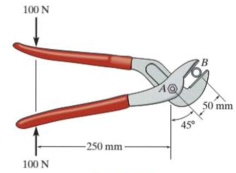
Prob. F5-15
Expert Solution & Answer
Want to see the full answer?
Check out a sample textbook solution
Students have asked these similar questions
6-127. Determine the clamping force exerted on the
smooth pipe at B if a force of 20 lb is applied to the handles
of the pliers. The pliers are pinned together at A.
20 lb
20 lb
10 in.
40°
1.5 in.
0.5 in.
B
R5-6. Determine the horizontal and vertical components
of force that the pins A and Cexert on the two-member frame.
500 N/m
-3m-
600 N/m
400 N/m
3-2. The members of a truss are pin connected at joint O.
Determine the magnitude of F, and its angle for
equilibrium. Set F - 6 KN.
5 kN
70
30
7 KN
Probs. 3-1/2
Chapter 5 Solutions
Statics and Mechanics of Materials (5th Edition)
Ch. 5.3 - In each ease, calculate the support reactions and...Ch. 5.3 - Identify the zero-force members in each truss....Ch. 5.3 - Determine the force in each member of the truss...Ch. 5.3 - Determine the force in each member of the truss...Ch. 5.3 - Determine the force in each member of the truss...Ch. 5.3 - Determine the greatest load P that can be applied...Ch. 5.3 - Identify the zero-force members in the truss....Ch. 5.3 - Determine the force in each member of the truss...Ch. 5.3 - Determine the force in each member of the truss...Ch. 5.3 - Determine the force in each member of the truss...
Ch. 5.3 - Determine the force in each member of the truss...Ch. 5.3 - Determine the force in each member of the truss...Ch. 5.3 - Determine the force in each member of the truss,...Ch. 5.3 - Determine the force in each member of the truss,...Ch. 5.3 - Determine the force in each member of the truss...Ch. 5.3 - Determine the force in each member of the truss in...Ch. 5.3 - Members AB and BC can each support a maximum...Ch. 5.3 - Members AB and BC can each support a maximum...Ch. 5.3 - Determine the force in each member of the truss...Ch. 5.3 - If the maximum force that any member can support...Ch. 5.3 - Determine the force in each member of the truss...Ch. 5.3 - Determine the force in each member of the truss...Ch. 5.3 - Determine the force in each member of the truss...Ch. 5.3 - Determine the force in each member of the truss...Ch. 5.4 - Determine the force in members BC, CF, and FE and...Ch. 5.4 - Determine the force in members LK, KC, and CD of...Ch. 5.4 - Determine the force in members KJ, KD, and CD of...Ch. 5.4 - Determine the force in members EF, CF, and BC of...Ch. 5.4 - Determine the force in members GF, GD, and CD of...Ch. 5.4 - Determine the force in members DC, HI, and JI of...Ch. 5.4 - Determine the force in members DC, HC and HI of...Ch. 5.4 - Determine the force in members ED, EH, and GH of...Ch. 5.4 - Determine the force in members HG, HE, and DE of...Ch. 5.4 - Determine the force in members CD, HI, and CH of...Ch. 5.4 - Determine the force in members CD, CJ, KJ, and DJ...Ch. 5.4 - Prob. 22PCh. 5.4 - The Howe truss is subjected to the loading shown....Ch. 5.4 - The Howe truss is subjected to the loading shown....Ch. 5.4 - Determine the force in members EF, CF, and BC, and...Ch. 5.4 - Determine the force in members AF, BF, and BC, and...Ch. 5.4 - Prob. 27PCh. 5.4 - Determine the force in members BC, BE, and EF of...Ch. 5.4 - Prob. 29PCh. 5.4 - Determine the force in members CD, CF, and CG and...Ch. 5.4 - Determine the force developed in members FE, EB,...Ch. 5.5 - In each ease, identify any two-force members, and...Ch. 5.5 - F5-13. Determine the force P needed to hold the...Ch. 5.5 - Determine the horizontal and vertical components...Ch. 5.5 - If a 100-N force is applied to the handles of the...Ch. 5.5 - Determine the horizontal and vertical components...Ch. 5.5 - Determine the force P required to hold the 100-lb...Ch. 5.5 - In each case, determine the force P required to...Ch. 5.5 - Determine the force P required to hold the 50-kg...Ch. 5.5 - Determine the force P required to hold the 150-kg...Ch. 5.5 - Determine the reactions at the supports A, C, and...Ch. 5.5 - Determine the resultant force at pins A, B, and C...Ch. 5.5 - Determine the reactions at the supports at A, E,...Ch. 5.5 - The wall crane supports a load of 700 lb....Ch. 5.5 - The wall crane supports a load of 700 lb....Ch. 5.5 - Determine the horizontal and vertical components...Ch. 5.5 - Determine the force in members FD and DB of the...Ch. 5.5 - Determine the force that the smooth 20-kg cylinder...Ch. 5.5 - The three power lines exert the forces shown on...Ch. 5.5 - The pumping unit is used to recover oil. When the...Ch. 5.5 - Determine the force that the jaws J of the metal...Ch. 5.5 - Prob. 47PCh. 5.5 - Prob. 48PCh. 5.5 - Prob. 49PCh. 5.5 - Determine the force created in the hydraulic...Ch. 5.5 - The hydraulic crane is used to lift the 1400-lb...Ch. 5.5 - Determine force P on the cable if the spring is...Ch. 5.5 - Prob. 53PCh. 5.5 - Prob. 54PCh. 5.5 - Prob. 55PCh. 5.5 - Determine the force P on the cable if the spring...Ch. 5.5 - Prob. 57PCh. 5.5 - Prob. 58PCh. 5.5 - Prob. 59PCh. 5.5 - Prob. 60PCh. 5.5 - The platform scale consists of a combination of...Ch. 5 - All the problems solutions must include FBDs....Ch. 5 - Determine the force in each member of the truss...Ch. 5 - Determine the force in member GJ and GC of the...Ch. 5 - Determine the force in members GF, FB, and BC of...Ch. 5 - Prob. 5RPCh. 5 - Determine the horizontal and vertical components...Ch. 5 - Prob. 7RPCh. 5 - Determine the resultant forces at pins B and C on...
Knowledge Booster


Learn more about
Need a deep-dive on the concept behind this application? Look no further. Learn more about this topic, mechanical-engineering and related others by exploring similar questions and additional content below.Similar questions
- Determine the n- and t-components of the force F which is exerted by the rod AB on the crank OA. Evaluate your general expression for F = 106 N and (a) e = 16°, B = 14° and (b) e = 23°, B = 30° B Answers: N, F =| N (a) Fn = N (b) Fo N, F =arrow_forwardR3-5. The joint of a space frame is subjected to four member forces. Member OA lies in the x-y plane and member OB lies in the y-z plane. Determine the force acting in each of the members required for equilibrium of the joint. Fs 200 N Prob. R3-5 Barrow_forwardDetermine the n- and t-components of the force F which is exerted by the rod AB on the crank OA. Evaluate your general expression for F = 118 N and (a) e = 30°, B = 25° and (b) e = 21°, B = 29° Answers: (a) Fn= i N, F: = i N (b) Fn = i N. F:= Narrow_forward
- *3-12. The concrete pipe elbow has a weight of 400 lb and the center of gravity is located at point G. Determine the force FAR and the tension in cables BC and BD needed to support it. FAB B 30 in, 45° 45° 30 in. D Garrow_forwardDetermine the n- and t-components of the force F which is exerted by the rod AB on the crank OA. Evaluate your general expression for F-119 N and (a) 0-24°, B-16° and (b) 0-24°, B-29⁰ Answers: (a) F- i N, F.- i N (b) Fi N. F i Narrow_forwardDetermine the n- and t-components of the force F which is exerted by the rod AB on the crank OA. Evaluate your general expression for F-101 N and (a) = 29°, -21° and (b) 0 -25°, 3 - 36° B Answers: (a) F= N (b) Fn- N i i N, F₂ i N. F iarrow_forward
- R4-1. If the roller at B can sustain a maximum load of 3 kN, determine the largest magnitude of each of the three forces F that can be supported by the truss. 45 -2 marrow_forwardQ-2: The woman exercises on the rowing machine. If she exerts a holding force of F = 350 N on handle ABD, determine the horizontal and vertical components of reaction at pin C and the force developed along the hydarulic cylinder BD on the handle. F = 350 N 30 0.25 m 0.25 m 0.82m- 0.18m 0.14marrow_forward*3-4. Cords AB and AC can each sustain a maximum tension of 800 lb. If the drum has a weight of 900 lb, determine the smallest angle 0 at which they can be attached to the drum. B. 10arrow_forward
- Determine the resultant force at pins A, B, and C on the three-member frame. Given: F = 40N, w = 10, L = 1.arrow_forward6-21. A force of P = 8 lb is applied to the handles of the pliers. Determine the force developed on the smooth bolt B and the reaction that pin A exerts on its attached members. P -5 in. +1.5 in.- 1.25 in. 1.25 in. P Prob. 6-21 A Barrow_forwardThe machine part of negligible weight is supported by a pin at A and a roller at C. Determine the magnitudes of the forces acting on the part 400 2.4 kN m 40° B at A and C. 250 300 200 3 kN Dimensions in mm DIFFICULT 2 Nc 50° 400 2.4 kN•m 40° A, 300 -200 250- 3 kN A,arrow_forward
arrow_back_ios
SEE MORE QUESTIONS
arrow_forward_ios
Recommended textbooks for you
 Elements Of ElectromagneticsMechanical EngineeringISBN:9780190698614Author:Sadiku, Matthew N. O.Publisher:Oxford University Press
 Mechanics of Materials (10th Edition)Mechanical EngineeringISBN:9780134319650Author:Russell C. HibbelerPublisher:PEARSON
 Thermodynamics: An Engineering ApproachMechanical EngineeringISBN:9781259822674Author:Yunus A. Cengel Dr., Michael A. BolesPublisher:McGraw-Hill Education
 Control Systems EngineeringMechanical EngineeringISBN:9781118170519Author:Norman S. NisePublisher:WILEY
 Mechanics of Materials (MindTap Course List)Mechanical EngineeringISBN:9781337093347Author:Barry J. Goodno, James M. GerePublisher:Cengage Learning
 Engineering Mechanics: StaticsMechanical EngineeringISBN:9781118807330Author:James L. Meriam, L. G. Kraige, J. N. BoltonPublisher:WILEY
Elements Of Electromagnetics
Mechanical Engineering
ISBN:9780190698614
Author:Sadiku, Matthew N. O.
Publisher:Oxford University Press
Mechanics of Materials (10th Edition)
Mechanical Engineering
ISBN:9780134319650
Author:Russell C. Hibbeler
Publisher:PEARSON
Thermodynamics: An Engineering Approach
Mechanical Engineering
ISBN:9781259822674
Author:Yunus A. Cengel Dr., Michael A. Boles
Publisher:McGraw-Hill Education
Control Systems Engineering
Mechanical Engineering
ISBN:9781118170519
Author:Norman S. Nise
Publisher:WILEY
Mechanics of Materials (MindTap Course List)
Mechanical Engineering
ISBN:9781337093347
Author:Barry J. Goodno, James M. Gere
Publisher:Cengage Learning
Engineering Mechanics: Statics
Mechanical Engineering
ISBN:9781118807330
Author:James L. Meriam, L. G. Kraige, J. N. Bolton
Publisher:WILEY
How to Measure Threads; Author: PracticalMachinist;https://www.youtube.com/watch?v=Uuy7EViS7Kc;License: Standard Youtube License