
Statics and Mechanics of Materials (5th Edition)
5th Edition
ISBN: 9780134382593
Author: Russell C. Hibbeler
Publisher: PEARSON
expand_more
expand_more
format_list_bulleted
Videos
Textbook Question
Chapter 5, Problem 6RP
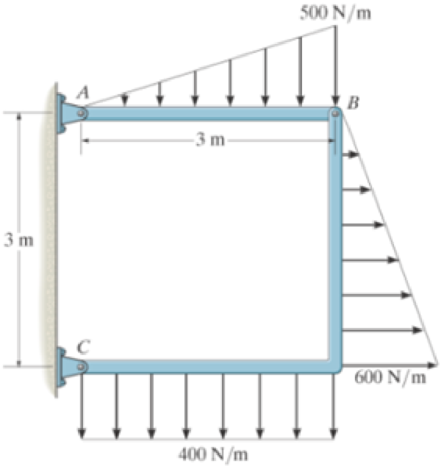
Determine the horizontal and vertical components of force at pins A and C of the two-member frame.
Prob. R6-7
R5-6. Determine the horizontal and vertical components of force that the pins A and C exert on the two-member frame.
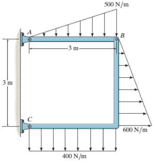
Prob. R5-6
Expert Solution & Answer
Want to see the full answer?
Check out a sample textbook solution
Students have asked these similar questions
6-85.
The three power lines exert the forces shown on the truss
joints, which in turn are pin-connected to the poles AH and
EG. Determine the force in the guy cable AI and the pin
reaction at the support H.
20 ft
D
B
-40 ft--40 ft-
800 lb
800 lb
H
800 lb
-50 ft-30 ft--30
20 ft
-30 ft-30 ft-30 ft-30 ft
30 ft-30
20 ft
ft-50 ft-
125 ft
3-2. The members of a truss are pin connected at joint O.
Determine the magnitude of F, and its angle for
equilibrium. Set F - 6 KN.
5 kN
70
30
7 KN
Probs. 3-1/2
6-21. A force of P = 8 lb is applied to the handles of the
pliers. Determine the force developed on the smooth bolt B
and the reaction that pin A exerts on its attached members.
P
-5 in.
+1.5 in.-
1.25 in.
1.25 in.
P
Prob. 6-21
A
B
Chapter 5 Solutions
Statics and Mechanics of Materials (5th Edition)
Ch. 5.3 - In each ease, calculate the support reactions and...Ch. 5.3 - Identify the zero-force members in each truss....Ch. 5.3 - Determine the force in each member of the truss...Ch. 5.3 - Determine the force in each member of the truss...Ch. 5.3 - Determine the force in each member of the truss...Ch. 5.3 - Determine the greatest load P that can be applied...Ch. 5.3 - Identify the zero-force members in the truss....Ch. 5.3 - Determine the force in each member of the truss...Ch. 5.3 - Determine the force in each member of the truss...Ch. 5.3 - Determine the force in each member of the truss...
Ch. 5.3 - Determine the force in each member of the truss...Ch. 5.3 - Determine the force in each member of the truss...Ch. 5.3 - Determine the force in each member of the truss,...Ch. 5.3 - Determine the force in each member of the truss,...Ch. 5.3 - Determine the force in each member of the truss...Ch. 5.3 - Determine the force in each member of the truss in...Ch. 5.3 - Members AB and BC can each support a maximum...Ch. 5.3 - Members AB and BC can each support a maximum...Ch. 5.3 - Determine the force in each member of the truss...Ch. 5.3 - If the maximum force that any member can support...Ch. 5.3 - Determine the force in each member of the truss...Ch. 5.3 - Determine the force in each member of the truss...Ch. 5.3 - Determine the force in each member of the truss...Ch. 5.3 - Determine the force in each member of the truss...Ch. 5.4 - Determine the force in members BC, CF, and FE and...Ch. 5.4 - Determine the force in members LK, KC, and CD of...Ch. 5.4 - Determine the force in members KJ, KD, and CD of...Ch. 5.4 - Determine the force in members EF, CF, and BC of...Ch. 5.4 - Determine the force in members GF, GD, and CD of...Ch. 5.4 - Determine the force in members DC, HI, and JI of...Ch. 5.4 - Determine the force in members DC, HC and HI of...Ch. 5.4 - Determine the force in members ED, EH, and GH of...Ch. 5.4 - Determine the force in members HG, HE, and DE of...Ch. 5.4 - Determine the force in members CD, HI, and CH of...Ch. 5.4 - Determine the force in members CD, CJ, KJ, and DJ...Ch. 5.4 - Prob. 22PCh. 5.4 - The Howe truss is subjected to the loading shown....Ch. 5.4 - The Howe truss is subjected to the loading shown....Ch. 5.4 - Determine the force in members EF, CF, and BC, and...Ch. 5.4 - Determine the force in members AF, BF, and BC, and...Ch. 5.4 - Prob. 27PCh. 5.4 - Determine the force in members BC, BE, and EF of...Ch. 5.4 - Prob. 29PCh. 5.4 - Determine the force in members CD, CF, and CG and...Ch. 5.4 - Determine the force developed in members FE, EB,...Ch. 5.5 - In each ease, identify any two-force members, and...Ch. 5.5 - F5-13. Determine the force P needed to hold the...Ch. 5.5 - Determine the horizontal and vertical components...Ch. 5.5 - If a 100-N force is applied to the handles of the...Ch. 5.5 - Determine the horizontal and vertical components...Ch. 5.5 - Determine the force P required to hold the 100-lb...Ch. 5.5 - In each case, determine the force P required to...Ch. 5.5 - Determine the force P required to hold the 50-kg...Ch. 5.5 - Determine the force P required to hold the 150-kg...Ch. 5.5 - Determine the reactions at the supports A, C, and...Ch. 5.5 - Determine the resultant force at pins A, B, and C...Ch. 5.5 - Determine the reactions at the supports at A, E,...Ch. 5.5 - The wall crane supports a load of 700 lb....Ch. 5.5 - The wall crane supports a load of 700 lb....Ch. 5.5 - Determine the horizontal and vertical components...Ch. 5.5 - Determine the force in members FD and DB of the...Ch. 5.5 - Determine the force that the smooth 20-kg cylinder...Ch. 5.5 - The three power lines exert the forces shown on...Ch. 5.5 - The pumping unit is used to recover oil. When the...Ch. 5.5 - Determine the force that the jaws J of the metal...Ch. 5.5 - Prob. 47PCh. 5.5 - Prob. 48PCh. 5.5 - Prob. 49PCh. 5.5 - Determine the force created in the hydraulic...Ch. 5.5 - The hydraulic crane is used to lift the 1400-lb...Ch. 5.5 - Determine force P on the cable if the spring is...Ch. 5.5 - Prob. 53PCh. 5.5 - Prob. 54PCh. 5.5 - Prob. 55PCh. 5.5 - Determine the force P on the cable if the spring...Ch. 5.5 - Prob. 57PCh. 5.5 - Prob. 58PCh. 5.5 - Prob. 59PCh. 5.5 - Prob. 60PCh. 5.5 - The platform scale consists of a combination of...Ch. 5 - All the problems solutions must include FBDs....Ch. 5 - Determine the force in each member of the truss...Ch. 5 - Determine the force in member GJ and GC of the...Ch. 5 - Determine the force in members GF, FB, and BC of...Ch. 5 - Prob. 5RPCh. 5 - Determine the horizontal and vertical components...Ch. 5 - Prob. 7RPCh. 5 - Determine the resultant forces at pins B and C on...
Knowledge Booster


Learn more about
Need a deep-dive on the concept behind this application? Look no further. Learn more about this topic, mechanical-engineering and related others by exploring similar questions and additional content below.Similar questions
- R3-5. The joint of a space frame is subjected to four member forces. Member OA lies in the x-y plane and member OB lies in the y-z plane. Determine the force acting in each of the members required for equilibrium of the joint. Fs 200 N Prob. R3-5 Barrow_forwardQ-2: The woman exercises on the rowing machine. If she exerts a holding force of F = 350 N on handle ABD, determine the horizontal and vertical components of reaction at pin C and the force developed along the hydarulic cylinder BD on the handle. F = 350 N 30 0.25 m 0.25 m 0.82m- 0.18m 0.14marrow_forward*6-76. Determine the horizontal and vertical components of force which the pins at A, B, and C exert on member ABC of the frame. 400 N -1.5 m- -2 m- 1.5 m 2.5 m – 300 N -B 2 m – 300 N 2.5 m 1.5 m Earrow_forward
- 6-39. The tongs consist of two jaws pinned to links at A, B, C, and D. Determine the horizontal and vertical components of force exerted on the 500-lb stone at F and G in order to lift it. 2 ft 1.5 ft 1 ft J B 1 ft1 ft E Prob. 6-39 Carrow_forward5-27. As an airplane's brakes are applied, the nose wheel exerts two forces on the end of the landing gear as shown. Determine the horizontal and vertical components of reaction at the pin C and the force in strut AB. 30 400 mm 20 600 mm 2 kN 6 kNarrow_forward6-89. Determine the horizontal and vertical components of force at each pin. The suspended cylinder has a weight of 80 lb. 4 ft 4 ft O E O A D O 3 ft- B 6 ft- Prob. 6-89 2 ft 1 ft of 3500 lb andarrow_forward
- 5-27. As an airplane's brakes are applied, the nose wheel exerts two forces on the end of the landing gear as shown. Determine the horizontal and vertical components of reaction at the pin C and the force in strut AB. B. 30° 400 mm 20° 600 mm 2 kN 6 kNarrow_forwardQ-2: The woman exercises on the rowing machine. If she exerts a holding force of F = 350 N on handle ABD, determine the horizontal and vertical components of reaction at pin C and the force developed along the hydarulic cylinder BD on the handle. F = 350 N 0.25 m 0.25m C 0.82m- 0.18m 0.14marrow_forwardProbs. 3-1/2 3 If the mass of the girder is 3 Mg and its center of mass is located at point G, determine the tension developed in cables AB, BC, and BD for equilibrium. FAB B 45° 30° D Probs. 3-3/4arrow_forward
- 5-28. The hatch door has a weight of 80 lb and cente gravity at G. If the force F applied to the handle at C coordinate direction angles of a = 60°, B = 45°, y = 60°, determine the magnitude of F needed to hold door slightly open as shown. The hinges are in pr alignment and exert only force reactions on the d Determine the components of these reactions if A ex only x and z components of force and B exerts x, y, z f components. z 4 ft ---3-72 3 ft C Prob. 5-28 B X Farrow_forward•5-21. Determine the horizontal and vertical components of reaction at the pin A and the tension developed in cable BC used to support the steel frame. 60 kN 1m-1m- 1 m- B 30 kN m 3 m 5 COarrow_forward3/3 The weight of the bicycle is 29 lb with center of grav- ity at G. Determine the normal forces at A and B when the bicycle is in equilibrium. B - 22.5"- -18.5"- Problem 3/3arrow_forward
arrow_back_ios
SEE MORE QUESTIONS
arrow_forward_ios
Recommended textbooks for you
 Elements Of ElectromagneticsMechanical EngineeringISBN:9780190698614Author:Sadiku, Matthew N. O.Publisher:Oxford University Press
 Mechanics of Materials (10th Edition)Mechanical EngineeringISBN:9780134319650Author:Russell C. HibbelerPublisher:PEARSON
 Thermodynamics: An Engineering ApproachMechanical EngineeringISBN:9781259822674Author:Yunus A. Cengel Dr., Michael A. BolesPublisher:McGraw-Hill Education
 Control Systems EngineeringMechanical EngineeringISBN:9781118170519Author:Norman S. NisePublisher:WILEY
 Mechanics of Materials (MindTap Course List)Mechanical EngineeringISBN:9781337093347Author:Barry J. Goodno, James M. GerePublisher:Cengage Learning
 Engineering Mechanics: StaticsMechanical EngineeringISBN:9781118807330Author:James L. Meriam, L. G. Kraige, J. N. BoltonPublisher:WILEY
Elements Of Electromagnetics
Mechanical Engineering
ISBN:9780190698614
Author:Sadiku, Matthew N. O.
Publisher:Oxford University Press
Mechanics of Materials (10th Edition)
Mechanical Engineering
ISBN:9780134319650
Author:Russell C. Hibbeler
Publisher:PEARSON
Thermodynamics: An Engineering Approach
Mechanical Engineering
ISBN:9781259822674
Author:Yunus A. Cengel Dr., Michael A. Boles
Publisher:McGraw-Hill Education
Control Systems Engineering
Mechanical Engineering
ISBN:9781118170519
Author:Norman S. Nise
Publisher:WILEY
Mechanics of Materials (MindTap Course List)
Mechanical Engineering
ISBN:9781337093347
Author:Barry J. Goodno, James M. Gere
Publisher:Cengage Learning
Engineering Mechanics: Statics
Mechanical Engineering
ISBN:9781118807330
Author:James L. Meriam, L. G. Kraige, J. N. Bolton
Publisher:WILEY
Mechanical SPRING DESIGN Strategy and Restrictions in Under 15 Minutes!; Author: Less Boring Lectures;https://www.youtube.com/watch?v=dsWQrzfQt3s;License: Standard Youtube License