
Structural Analysis (MindTap Course List)
5th Edition
ISBN: 9781133943891
Author: Aslam Kassimali
Publisher: Cengage Learning
expand_more
expand_more
format_list_bulleted
Videos
Textbook Question
Chapter 5, Problem 54P
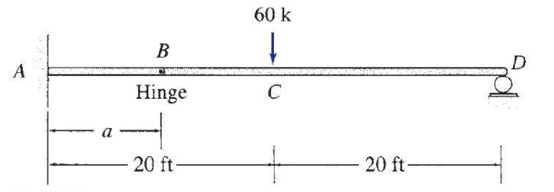
For the beam shown: (a) determine the distance a for which the maximum positive and negative bending moments in the beam are equal; and (b) draw the corresponding shear and bending moment diagrams for the beam.
Expert Solution & Answer

Trending nowThis is a popular solution!

Students have asked these similar questions
B.2.
Elementary beam theory predicts that the axial bending stress ox in a
prismatic beam is given by:
σ, X
(M.1, M,1,)y+ (M, I. - M.1,-) z
(1,1.-1²-)
where My and M₂ are bending moments applied to a cross-section, and
where ly, Iz and lyz are second moments of area in the usual notation
(Oxyz is a Cartesian coordinate system in which the x axis corresponds
to the centroidal axis of the beam).
(i) What assumptions have been made in the derivation of the
above expression?
(ii) Indicate by means of a sketch the directions in which positive
values of the bending moments My and M₂ act on a cut plane
facing in the positive x direction.
complete solution
Determine (a) the maximum bending stress and (b)the maximum shearing stress due to V in the simplysupported beam shown in the figure.
The beam is supported by a roller at B and a pin at C and is subjected to the distributed load shown with
intensity w = 180 N/m. The maximum positive and negative internal bending moments are critical factors
in the design of the beam material and geometry. Determine the largest positive and negative internal
bending moments that occur in the beam and the points along the length where each occurs. Take z = 0
to be at point A at the left edge of the beam.
cc 1❀0
BY NC SA
2016 Eric Davishahl
a
X
b
-a-
4.00 m
5.20 m
B
Values for dimensions on the figure are given in the following table. Note the figure may not be to scale.
Variable Value
The maximum negative internal bending moment is
and occurs at z =|
m to the right of A.
The maximum positive internal bending moment is
and occurs at x =
W
m to the right of A.
·b-
N-m
N-m
Chapter 5 Solutions
Structural Analysis (MindTap Course List)
Ch. 5 - Prob. 1PCh. 5 - Prob. 2PCh. 5 - Prob. 3PCh. 5 - Prob. 4PCh. 5 - Prob. 5PCh. 5 - Prob. 6PCh. 5 - Prob. 7PCh. 5 - Prob. 8PCh. 5 - Prob. 9PCh. 5 - Prob. 10P
Ch. 5 - Prob. 11PCh. 5 - Determine the equations for shear and bending...Ch. 5 - Determine the equations for shear and bending...Ch. 5 - Determine the equations for shear and bending...Ch. 5 - Determine the equations for shear and bending...Ch. 5 - Determine the equations for shear and bending...Ch. 5 - Prob. 17PCh. 5 - Determine the equations for shear and bending...Ch. 5 - 5.12 through 5.28 Determine the equations for...Ch. 5 - 5.12 through 5.28 Determine the equations for...Ch. 5 - 5.12 through 5.28 Determine the equations for...Ch. 5 - 5.12 through 5.28 Determine the equations for...Ch. 5 - 5.12 through 5.28 Determine the equations for...Ch. 5 - 5.12 through 5.28 Determine the equations for...Ch. 5 - Prob. 25PCh. 5 - 5.12 through 5.28 Determine the equations for...Ch. 5 - Prob. 27PCh. 5 - 5.12 through 5.28 Determine the equations for...Ch. 5 - Prob. 29PCh. 5 - Prob. 30PCh. 5 - 5.29 through 5.51 Draw the shear and bending...Ch. 5 - 5.29 through 5.51 Draw the shear and bending...Ch. 5 - 5.29 through 5.51 Draw the shear and bending...Ch. 5 - Prob. 34PCh. 5 - 5.29 through 5.51 Draw the shear and bending...Ch. 5 - Prob. 36PCh. 5 - 5.29 through 5.51 Draw the shear and bending...Ch. 5 - 5.29 through 5.51 Draw the shear and bending...Ch. 5 - Prob. 39PCh. 5 - Prob. 40PCh. 5 - 5.29 through 5.51 Draw the shear and bending...Ch. 5 - 5.29 through 5.51 Draw the shear and bending...Ch. 5 - 5.29 through 5.51 Draw the shear and bending...Ch. 5 - Prob. 44PCh. 5 - Prob. 45PCh. 5 - 5.29 through 5.51 Draw the shear and bending...Ch. 5 - 5.29 through 5.51 Draw the shear and bending...Ch. 5 - 5.29 through 5.51 Draw the shear and bending...Ch. 5 - 5.29 through 5.51 Draw the shear and bending...Ch. 5 - 5.29 through 5.51 Draw the shear and bending...Ch. 5 - 5.29 through 5.51 Draw the shear and bending...Ch. 5 - Draw the shear and bending moment diagrams for the...Ch. 5 - For the beam shown: (a) determine the distance a...Ch. 5 - For the beam shown: (a) determine the distance a...Ch. 5 - Prob. 55PCh. 5 - Prob. 56PCh. 5 - Prob. 57PCh. 5 - Prob. 58PCh. 5 - Prob. 59PCh. 5 - Prob. 60PCh. 5 - Prob. 61PCh. 5 - Prob. 62PCh. 5 - Prob. 63PCh. 5 - Prob. 64PCh. 5 - Prob. 65PCh. 5 - Prob. 66PCh. 5 - Prob. 67PCh. 5 - Prob. 68PCh. 5 - Prob. 69PCh. 5 - Prob. 70PCh. 5 - Prob. 71P
Knowledge Booster


Learn more about
Need a deep-dive on the concept behind this application? Look no further. Learn more about this topic, civil-engineering and related others by exploring similar questions and additional content below.Similar questions
- There is a statically indeterminate beam in which the horizontal force at the left and right ends (points A and D) is zero, and the vertical force is shown in the figure below, The flexural stiffness of the beam section is constant El: (a) Find the (bending moment) reaction forces at points A and D.arrow_forwardThe bending moment diagram is constant for an interval of a beam then the crossponding shear force diagram is an inclined straight line. A curved line. A line parallel to the axis. A zero linearrow_forwardProblem 2 -A concentrated couple, = 600 Nm acts at the center of the simply Supported beam which is also asted upon by the distributed load shown in the figure. Assume that the beam itself is weightless. (a) Find the internal shear Vx) and moment M(x) as a functions of x. (b) Draw the shear and moment diagrams. Label the values at x = 0, x = 6, x = 12, and at any point where V(x) or M(x) is a local maximum or minimum. y 50 N/m Mo 6 m 6 marrow_forward
- for the beam and loading shown (a)use discontinnuity functions to write the expression for w(x). include the beam reactions in this expression. (B) intergrate w(x) twice to determine v(x) and m(x). (C) Use v(x) and m(x) to plot the shear- force and bending- moment diagrams.arrow_forwardIn the overconnected plane truss system, where the loading condition is given in the figure, the elongation stiffness in all bars is EA. Calculate the rod forces using the force method.arrow_forwardFor the beam shown below, use your preferred method and determine:a. The reactions at the supports (Ray, Rbx, Rby). b. The shear force diagram. c. The bending moment diagram.arrow_forward
- Determine the bending stress at point A of the beam using the result obtained in Prob. 6–106. The moments of inertia of the cross-sectional area about the z and y axes are Iz = Iy = 5.561 in4 and the product of inertia of the cross sectional area with respect to the z and y axes is Iyz = −3.267 in4. (See Appendix A.)arrow_forwardbe L.A prismatic beam fixed at both ends carries a uniformly distributed load. The ratio of bending moment at supports to bending moment at midspan isarrow_forwardStart with the shear diagram. To use a segment of the left end of the beam to develop the expression for the shear, the vertical reaction at A must be known. Calculate the vertical reaction at A. Let a positive force act up. Write an expression for the internal shear for an arbitrary point between A and B. Write an expression for the internal shear for an arbitrary point between B and C. Draw the shear diagram for the beam. Write an expression for the bending moment at an arbitrary point between A and B. Use the standard sign convention for the internal moment for a beam. Write an expression for the bending moment at an arbitrary point between B and C. Draw the moment diagram for the beam.arrow_forward
- In the structures shown below all members have the same Young's Modulus, E, second moment of area, I, and cross sectional area, A. (a) Calculate the vertical deflection of the point load in the structure shown below. L A L (b) Using the principle of virtual work, calculate the internal forces in all the members in the structure shown below L A в (c) State all the assumptions. Barrow_forwardFor the cantilever beam shown in the figure, Find the:a) Support reactions b) Draw the shear and moment diagram c) Find the maximum bending stress in the rectangular wooden beamarrow_forwardA simply supported beam of length L is subjected to a varying distributed load sin (3x/L) Nm-¹, where the distance x is measured from the left support. The magnitude of the vertical reaction force in N at the left support isarrow_forward
arrow_back_ios
SEE MORE QUESTIONS
arrow_forward_ios
Recommended textbooks for you

 Structural Analysis (10th Edition)Civil EngineeringISBN:9780134610672Author:Russell C. HibbelerPublisher:PEARSON
 Principles of Foundation Engineering (MindTap Cou...Civil EngineeringISBN:9781337705028Author:Braja M. Das, Nagaratnam SivakuganPublisher:Cengage Learning
 Fundamentals of Structural AnalysisCivil EngineeringISBN:9780073398006Author:Kenneth M. Leet Emeritus, Chia-Ming Uang, Joel LanningPublisher:McGraw-Hill Education
 Traffic and Highway EngineeringCivil EngineeringISBN:9781305156241Author:Garber, Nicholas J.Publisher:Cengage Learning
Structural Analysis (10th Edition)
Civil Engineering
ISBN:9780134610672
Author:Russell C. Hibbeler
Publisher:PEARSON
Principles of Foundation Engineering (MindTap Cou...
Civil Engineering
ISBN:9781337705028
Author:Braja M. Das, Nagaratnam Sivakugan
Publisher:Cengage Learning
Fundamentals of Structural Analysis
Civil Engineering
ISBN:9780073398006
Author:Kenneth M. Leet Emeritus, Chia-Ming Uang, Joel Lanning
Publisher:McGraw-Hill Education
Traffic and Highway Engineering
Civil Engineering
ISBN:9781305156241
Author:Garber, Nicholas J.
Publisher:Cengage Learning
Introduction to Materials; Author: Industrial Heating;https://www.youtube.com/watch?v=R8EV8R8f5Tw;License: Standard Youtube License