
Find the axial force, shear force, and bending moments at points A and B of the given beam.
Answer to Problem 1P
The axial force at point A is
The shear force at point A is
The bending moment at point A is
The axial force at point B is
The shear force at point B is
The bending moment at point B is
Explanation of Solution
Given information:
The point load acting at the distance of 5 m from the left support
The inclined point load acting at the distance of 10 m from the left support
The point load acting at the distance of 15 m from the left support
Sign conversion:
Apply the sign convention for calculating the equations of equilibrium as below.
- For the horizontal forces equilibrium condition, take the force acting towards right side as positive
- For the vertical forces equilibrium condition, take the upward force as positive
- For moment equilibrium condition, take the clockwise moment as negative and counter clockwise moment as positive.
Apply the following sign convention for calculating the axial forces, shear and bending moments.
- When the portion of the beam considered is left of the section, then the external force acting to the left are considered as positive.
- When the portion of the beam considered is right of the section, then the external force acting to the right are considered as positive.
- When the portion of the beam considered is left of the section, then the external force acting upward are considered as positive.
- When the portion of the beam considered is right of the section, then the external force acting downward are considered as positive.
- When the portion of the beam considered is left of the section, then the clockwise moments are considered as positive.
- When the portion of the beam considered is right of the section, then the counterclockwise moments are considered as positive.
Calculation:
Draw the free body diagram of the entire beam as in Figure (1).
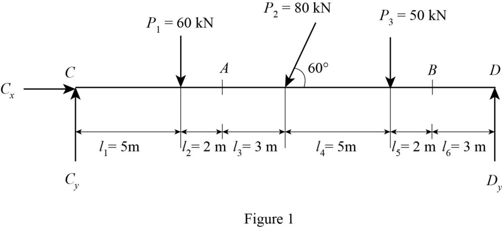
Determine the horizontal force at point C using equilibrium condition.
Substitute 80 kN for
Consider clockwise moment as positive and counter clockwise moment as negative.
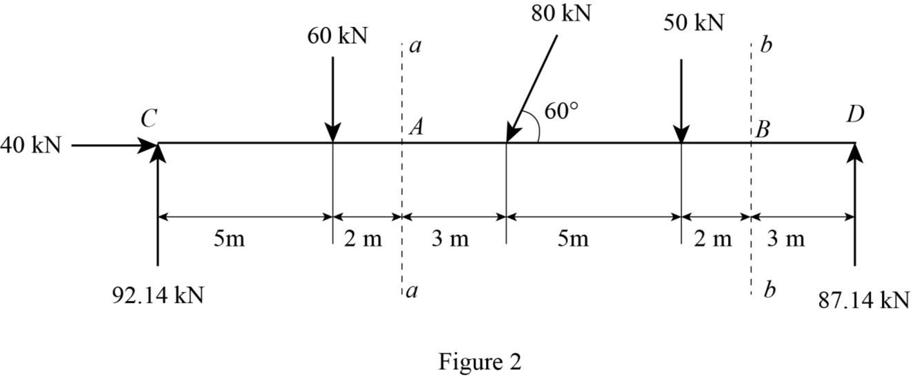
Determine the vertical force at the left support using equilibrium condition.
Taking moment about point D.
Substitute 20 m for L, 60 kN for
Determine the vertical force at the right support using equilibrium condition.
Substitute 92.14 kN for
Pass the sections aa and bb at points A and B respectively.
Draw the sections aa and bb as in Figure (2).
Consider section aa.
Show the free-body diagram of the left side of the section aa as in Figure 3.
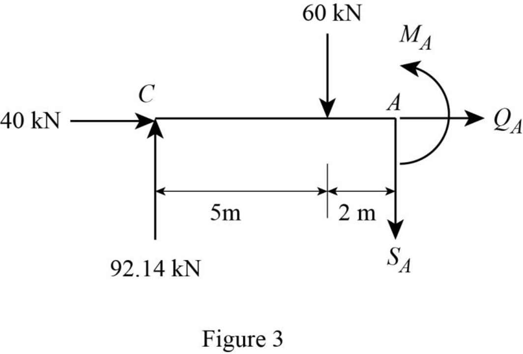
Axial force:
Consider the external forces acting to the left as positive.
Find the axial force at point A by resolving the horizontal equilibrium.
Therefore, the axial force at point A is
Shear force:
Consider the external forces acting upward as positive.
Determine the shear at point A using the relation.
Substitute 92.14 kN for
Therefore, the shear force at point A is
Bending moment:
Consider the clockwise moments of the external forces about A as positive.
Determine the moment at point A equilibrium equations.
Taking moment about point A.
Substitute 92.14 kN for
Therefore, the bending moment at point A is
Consider section bb:
Consider the right side of the section bb for calculation of internal forces.
Show the free-body diagram of the right side of the section bb as in Figure 4.
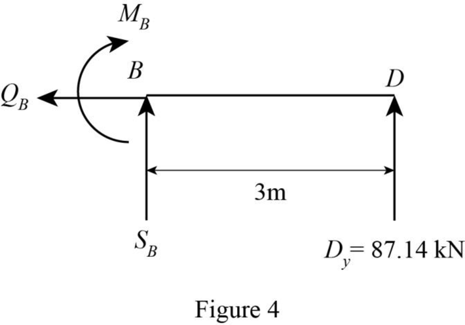
Axial force:
Find the axial force at point B by resolving the horizontal equilibrium.
Therefore, the axial force at point B is
Shear force:
Determine the shear at point B using the relation.
Substitute 87.14 kN for
Therefore, the shear force at point B is
Bending moment:
Consider the counter clockwise moments of the external forces about B as positive.
Determine the moment at point B equilibrium equations.
Taking moment about point B.
Substitute 87.14 kN for
Therefore, the bending moment at point B is
Want to see more full solutions like this?
Chapter 5 Solutions
Structural Analysis (MindTap Course List)

- You are replacing drinking water pipes in Asheville, NC. In one location, you must convey 10 ft³/s of drinking water with a pressure head drop of 1 ft per 1000 ft of horizontal pipe. If you are using commercial steel pipes, what is the diameter of pipe required to meet this need?arrow_forwardkN.m/m. Find Wn if M₁= -25 kN.m/m, Mg= -35 kN.m/m and Mc=+15 1 We 3X W +3(8-X) *w* 1 1 1 1 Wi 25 3 +35*3*. +15*3* + =?? X 8-x X 8-X We-Wi 3m ??=?? - W=?? dw =??= 0 -> X =??m dx Wn=?? kN/m² -L-8m 9 X +8-x- 3marrow_forwardSolve this pin-jointed truss using either method of joints (prefearably) or method by sections W= 30 kN P= 30kN a= 1m Attempted this question multiple times however i am strugguling. Please help with detailed work out calculations on paper, AC, BD, CD member forces finding vertical and horizontal members. ALSO no AI generated solution as this is absolutly not helpful. I will upvote if detailed solution (calculations) provided, THANK YOUarrow_forward
- I need detailed help solving this exercise from homework of Foundation Engineering. I do not really understand how to draw sub-item 3 and 4, please do it step by step, not that long but clear. Thank you!arrow_forwardI will rate you with UPVOTE, if it is COMPLETE STEP-BY-STEP CALCULATION. If it is INCOMPLETE SOLUTION and there are SHORTCUTS OF SOLUTION or AI GENERATED, I will rate you with DOWNVOTE. THANK YOU FOR YOUR HELP. PS: If you have answered this already, DON'T ANSWER IT AGAIN PLEASE i believe ur answers to be wrong; give chance to OTHER EXPERTS to answer it. I want to verify if all of you will arrive in the same final answer; thats why I ask it multiple times. If you answer it again, i'll DISLIKE all your entries/answers. Question The pin-jointed plane frame (truss) in the picture below use the method of virtual work to determine the vertical deflection at joint D and the horizontal deflection at joint B. All members of the truss have a constant EA of 1×10⁵kN. I have attempted the first half of the question however struggling at the second part. Actual working out of the joint section AC,BD, CD and the deflection table of each member by hand on paper for better comprehension. I do NOT…arrow_forwardWhat would be the best way to address safety hazards involving the construction of a high-rise building?arrow_forward
- The pin-jointed plane frame (truss) in the picture below use the method of virtual work to determine the vertical deflection at joint D and the horizontal deflection at joint B. All members of the truss have a constant EA of 1×10⁵kN. I have attempted the first half of the question however struggling at the second part. Actual working out of the joint section AC,BD, CD and the deflection table of each member for better comprehension. I do NOT need written do list but the calculation please! I will upvote, if answer is detailed (calculations) Thank you random picks for loads and dimensions:W = 30 kN P= 30 kN a= 1marrow_forwardThere are five possible routes from Shoridan to Mythaca with the following linkperformance functions:t1 = 18 + 4.5x1t2 = 21 + 7.0x2t3 = 26 + 4.9x3t4 = 29 + 3.4x4t5 = 34 + 0.3x5where ti is in minutes and xi is in 1,000 vehicles per hour.a) It is expected that 8,300 vehicles will be making the Shoridan- Mythaca trip in the maximumflow hour, determine the equilibrium flow on the five routes? Will all five routes be used?b) A transportation planner in Mythaca has tried to convert the expected flow and the linkperformance functions above into route floes. His solution includes x1 = 3.50, x2 = 2.82, and x3 =1.58. Do these values seem correct to you?arrow_forward1. The maximum required load on the compound beam shown below is to be designed in this problem. Beam ABC, found to have an internal hinge at B, is supported by a fixed support at A and a roller support at C. Beam DEF then supports beam ABC and is supported by a pin at F. Beam DEF rests on a smooth surface at section DE. If the flexural and shear stresses on both beams are limited to 70 MPa and 25 MPa, respectively, solve for the maximum allowable value of P. The cross-sections of both beams are shown. (Hint: Draw separate shear and bending moment diagram for each beam.) [19.0437 kN] 30P (TOTAL) 2.5P 9P (TOTAL) Beam ABC Beam DEF 350 mm 150 mm Provide the complete solutions for determining the reactions of the two beams, along with the shear and bending moment diagrams for each beam. Ensure all computations are carried out using the Area Method. 700 mm 300 mmarrow_forward
- For the semi-circular arch shown in diagram. draw shear and bending moment 3 m B 5 kNarrow_forward5. A 40 ft straight steel beam with a 4" x 6" rectangular cross-section is installed when the temperature is 40°F. It is supported in such a manner as to allow only 0.5 in longitudinal expansion. Lateral support is provided in each direction every 10 ft along the length of the beam. What is the largest temperature increase that the beam can withstand without buckling. The coefficient of thermal expansion, α = 6.60(106)/°F, and E = 29000 ksi. Assume pinned connections at each end and at each lateral support location. a) 195°F b) 140°F c) 340°F d) 300°Farrow_forwardThe pin-jointed plane frame (truss) in the picture below use the method of virtual work to determine the vertical deflection at joint D and the horizontal deflection at joint B. All members of the truss have a constant EA of 1×10⁵kN. I have attempted the first half of the question however struggling at the second part. Detail answer with actual working out of the joint section AC,BD, CD and the deflection table of each member for better comprehension. I do not need written do list but the calculation pls! I will upvote, if answer is detailed (calculations) Thank you random picks for loads and dimensions:W = 30 kN P= 30 kN a= 1marrow_forward

 Structural Analysis (10th Edition)Civil EngineeringISBN:9780134610672Author:Russell C. HibbelerPublisher:PEARSON
 Principles of Foundation Engineering (MindTap Cou...Civil EngineeringISBN:9781337705028Author:Braja M. Das, Nagaratnam SivakuganPublisher:Cengage Learning
 Fundamentals of Structural AnalysisCivil EngineeringISBN:9780073398006Author:Kenneth M. Leet Emeritus, Chia-Ming Uang, Joel LanningPublisher:McGraw-Hill Education
 Traffic and Highway EngineeringCivil EngineeringISBN:9781305156241Author:Garber, Nicholas J.Publisher:Cengage Learning