
Concept explainers
Videos
Find the Thevenin equivalent of the circuit.
Answer to Problem 45E
The Thevenin voltage is
Explanation of Solution
Calculation:
The redrawn circuit diagram is given in Figure 1,
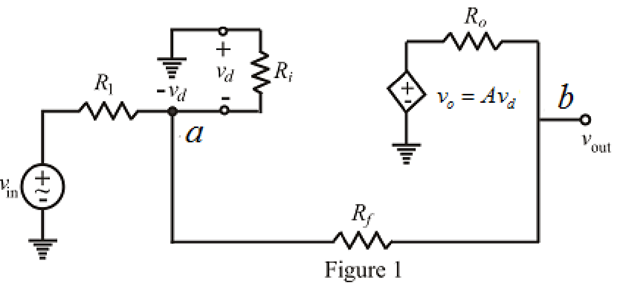
Refer to Figure 1,
Apply Kirchhoff’s current law at node
Here,
Rearrange equation (1),
Apply Kirchhoff’s current law at node
Here,
Substitute
Rearrange for
Substitute
Rearrange the equation for
Modify the equation as,
Write the equation to find voltage
So, the Thevenin voltage is
To find equivalent resistance of a circuit the independent voltage source replaced by short circuit and load resistor is disconnected and
The redrawn circuit diagram is given in Figure 2,
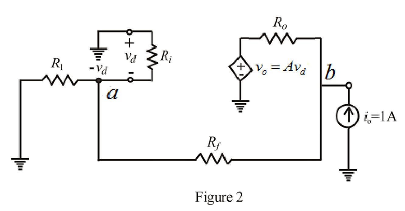
Refer to the redrawn Figure 2,
Apply Kirchhoff’s current law at node
Rearrange for
Apply Kirchhoff’s current law at node
Substitute
Substitute
Rearrange for
The expression for the Thevenin equivalent resistance is as follows,
Substitute
So, the Thevenin equivalent resistance is
The Thevenin equivalent circuit is drawn as shown in Figure 3,
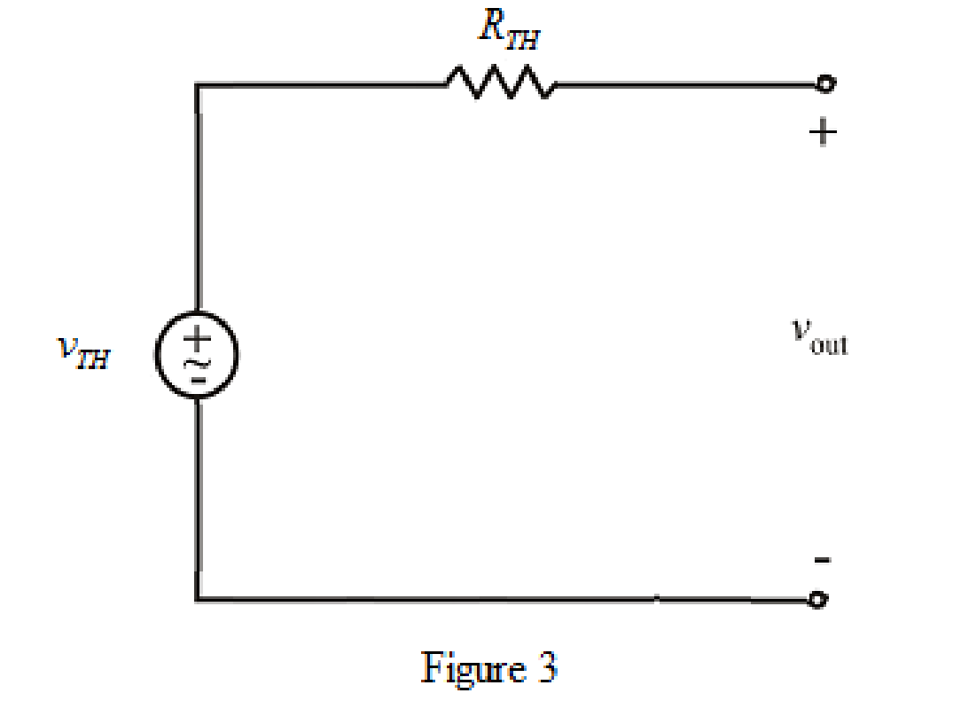
Conclusion:
Thus, the Thevenin voltage is
Want to see more full solutions like this?
Chapter 5 Solutions
Loose Leaf for Engineering Circuit Analysis Format: Loose-leaf


- QI:A: Design a multi-range ammeter of 0.5 and 1 Amp. using a PMMC(galvanometer) of 500 internal resistance and full-scale current of 1 ma. Show the way of connection with the load Rarrow_forwardKindly create a circuit with amplifier with DC power supply and with a gain of 150 with a closed circuit. Kindly provide explanation on how it operates thankyouarrow_forwardDESIGN PROJECT Single-Stage Common Emitter Class A AmplifierVoltage Divider Bias Circuit Supply: 10 Vdc to 24 VdcLoad: 1 kΩVoltage Gain: 80 to 400Lower Cutoff Frequency: 100 HzSinusoidal source (zero internal resistance): 50 mVp−pTransistor: Si, β = 75;Base-Collector capacitance= 8 pF; Base-Emitter Capacitance= 25 pFarrow_forward
- Please write down the meaning and functioning of the above amplifiersarrow_forwardWhich of the following is/are the characteristics of ideal amplifiers? 1. Open loop profits are infinite II. Bandwidth is infinite III. Output resistance is infinite Please choose one: A.I, II, III b. I, II C. Lonely II D. LOnely I e. Lonely IIIarrow_forwardDesign a three ip amp instrumentation amplifier having gain 20.arrow_forward
- Assume that the op amp in the circuit shown is ideal. 1. Calculate vo for the following values of vs: 0.4, 2.0, 3.5, −0.6, −1.6, and −2.4 V. 2. Specify the range of vs required to avoid amplifier saturation.arrow_forwardCalculate the voltage ratio vo/vs for the op amp circuit of Fig. 5.51. Assume that the op amp is ideal.arrow_forward5.37 Determine the output of the summing amplifier in Fig 5.74arrow_forward
 Introductory Circuit Analysis (13th Edition)Electrical EngineeringISBN:9780133923605Author:Robert L. BoylestadPublisher:PEARSON
 Delmar's Standard Textbook Of ElectricityElectrical EngineeringISBN:9781337900348Author:Stephen L. HermanPublisher:Cengage Learning
 Programmable Logic ControllersElectrical EngineeringISBN:9780073373843Author:Frank D. PetruzellaPublisher:McGraw-Hill Education
 Fundamentals of Electric CircuitsElectrical EngineeringISBN:9780078028229Author:Charles K Alexander, Matthew SadikuPublisher:McGraw-Hill Education
 Electric Circuits. (11th Edition)Electrical EngineeringISBN:9780134746968Author:James W. Nilsson, Susan RiedelPublisher:PEARSON
 Engineering ElectromagneticsElectrical EngineeringISBN:9780078028151Author:Hayt, William H. (william Hart), Jr, BUCK, John A.Publisher:Mcgraw-hill Education,