
Videos
The small−signal parameters of the NMOS transistor in the ac equivalent common−gate circuit shown in Figure P4.47 are
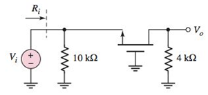
Figure P4.47
Want to see the full answer?
Check out a sample textbook solution
Chapter 4 Solutions
Microelectronics: Circuit Analysis and Design


- QUESTION 4 In this voltage divider bias circuit, the input is at the base. Output is at the emitter with a high input resistance and low output resistance. The maximum voltage gain is 1 and the coupling capacitors must have a negligible reactance at the frequency of operation. (use to answer a and b) a. Derive the expression for the voltage gain, current gain, and power gain in terms of power delivered to the load, RL. b. Sketch both the DC and AC equivalent circuits. c. Derive the expression for ripple factor of Half Wave Rectification with a capacitor filter.arrow_forwardAs shown in Figure Q4.1, ten diodes are to be operated in series in a 5000V peak string voltage application. The reverse-blocking voltage of the diodes is 600V and their maximum device reverse leakage current is 4mA. For worst case conditions, calculate the maximum value of sharing resistance R and the power dissipation of resistors and diodes.arrow_forwardExample 4.5: Small-Signal Model · Consider the circuit shown in Figure 4.14(a) for the case in which R = 10kOhm. The power supply V* has a dc value of 10V over which is super-imposed a 60HZ sinusoid of 1V peak amplitude (known as the supply ripple) - Q: Calculate both the dc voltage of the diode and the amplitude of the sine-wave signal observed across the diode. · Assume diode to have 0.7V drop at 1mA current. 52 A V+ A 10 V ER + UD (a) (b) R + (c) Figure 4.14: (a) circuit for Example 4.5. (b) circuit for calculating the dc operating point. (c) small-signal equivalent circuit. 53arrow_forward
- 4.70 A full-wave bridge-rectifier circuit with a 500-2 load operates from a 120-V (rms) 60-Hz houschold supply through a 6-to-1 step-down transformer having a single secondary winding. It uses four diodes, each of which can be modeled to have a 0.7-V drop for any current. What is the peak value of the rectified voltage across the load? For what fraction of a cycle does each diode conduct? What is the average voltage across the load? What is the average current through the load? 6:1 120 V rms 20 Vms 10.5 kN D2 D3 Vp = 0.7 V ணarrow_forwardSolve for Collector Resistance (RC)arrow_forward4.68 A half-wave rectifier circuit with a 500-2 load oper- ates from a 120-V (rms) 60-Hz household supply through a 12-to-1 step-down transformer. It uses a silicon diode that can be modeled to have a 0.7-V drop for any current. What is the peak voltage of the rectified output? For what fraction of the cycle does the diode conduct? What is the average output voltage? What is the average current in the load?arrow_forward
- 4.69 A full-wave rectifier circuit with a 1-k2 load operates from a 120-V (rms) 60-Hz household supply through a 5-to- 1 transformer having a center-tapped secondary winding. It uses two silicon diodes that can be modeled to have a 0.7-V drop for all currents. What is the peak voltage of the recti- fied output? For what fraction of a cycle does each diode conduct? What is the average output voltage? What is the average current in the load?arrow_forwardFigure Q4.c shows an alternative regulator circuit that could be used in a DC powersupply design to regulate the output of a rectifier. Determine the suitability of the regulator for a rectifier with the output specifications asgiven in Table 4. The ripple voltage of the rectifier is 30% of Vpk, and the regulatorneeds to deliver to the load the current of Io mA.The Zener diode power rating is 2W. The required output voltage is 7.4V. For the circuit in Figure Q4.c: determine the required Zener diode voltage Vz; find a suitable value of the resistor R; determine the minimum requirement for the transistor power rating PTR. 2) What is the role of the resistor R in this circuit? Show your working throughout and state any assumptions you may make.Provide commentary to your design process, and evaluate your design.arrow_forwardFor the circuit given in figure below draw the collector characteristic curves for IB = 50,150 and 250 micro amperes on the same grapharrow_forward
- 4.69 A full-wave rectifier circuit with a 500-2 load operates from a 120-V (rms) 60-Hz household supply through a 6-to-1 transformer having a center-tapped secondary winding. It uses two silicon diodes that can be modeled to have a 0.7-V drop for all currents. What is the peak voltage of the rectified output? For what fraction of a cycle does each diode conduct? What is the average output voltage? What is the average current in the load? Hint: the average output voltage can be obtained by using the equation below (see plots below too), but you will need to find out the conduction angle 0 first. T-0 1 - | (10/Zsinp – 0.7)dø v0,avg D1 Us, Vo (V) 6:1 Us 10 V 10 Vans C0.5 k2 0.7 v- 120 Vrms T-0 60 Hz D2 10 Vns mmarrow_forwardQ4. For the circuit shown in Figure Q4: i) What is the type of MOSFET and the amplifier configuration? ii) Find the Q-point (Ip and Vps) iii) What is the device transconductance, gm? iv) What are the voltage gain and output voltage? v) Draw the input /output voltage waveforms showing the phase relationship between them. Be sure to label them properly. +20V IDON = 15 mA@ VcsON = 6V VGSTH = 1V 1kQ Rp C2 10M2 Ro1 out Vin 3.3MQ Ra, 47003 Rs 50mV Figure Q4arrow_forwarda ): The depletion region is a layer of positive and negative charge in the semiconductormaterial Briefly explain how the depletion region formed in the semiconductormaterial after the PN junction is created.b): An audio signal amplifier is used to reproduce input audio signals at sound-producoutput elements, with desired volume and power levels. What is the function of volumecontrol and power amplifier in an audio signal amplifier ?arrow_forward
 Introductory Circuit Analysis (13th Edition)Electrical EngineeringISBN:9780133923605Author:Robert L. BoylestadPublisher:PEARSON
 Delmar's Standard Textbook Of ElectricityElectrical EngineeringISBN:9781337900348Author:Stephen L. HermanPublisher:Cengage Learning
 Programmable Logic ControllersElectrical EngineeringISBN:9780073373843Author:Frank D. PetruzellaPublisher:McGraw-Hill Education
 Fundamentals of Electric CircuitsElectrical EngineeringISBN:9780078028229Author:Charles K Alexander, Matthew SadikuPublisher:McGraw-Hill Education
 Electric Circuits. (11th Edition)Electrical EngineeringISBN:9780134746968Author:James W. Nilsson, Susan RiedelPublisher:PEARSON
 Engineering ElectromagneticsElectrical EngineeringISBN:9780078028151Author:Hayt, William H. (william Hart), Jr, BUCK, John A.Publisher:Mcgraw-hill Education,