
Machine Elements in Mechanical Design (6th Edition) (What's New in Trades & Technology)
6th Edition
ISBN: 9780134441184
Author: Robert L. Mott, Edward M. Vavrek, Jyhwen Wang
Publisher: PEARSON
expand_more
expand_more
format_list_bulleted
Concept explainers
Videos
Textbook Question
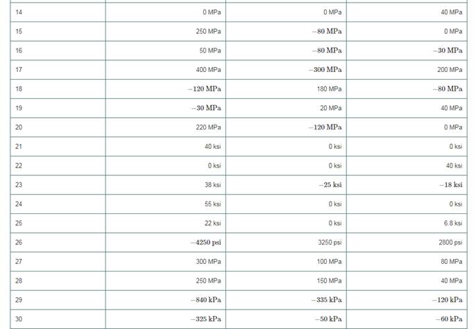
Chapter 4, Problem 2P
For the sets of given stresses on an element given in Table4−2, draw a complete Mohr’s circle, find the principal stresses and the maximum shear stress, and draw the principal stress element and the maximum shear stress element. Any stress components not shown are assumed to be zero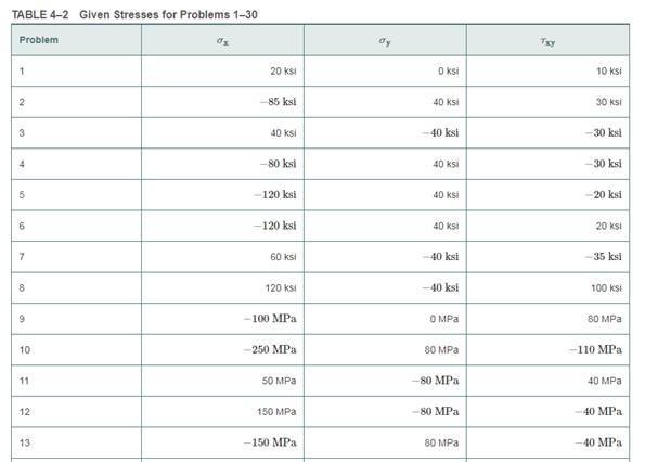
Expert Solution & Answer
Want to see the full answer?
Check out a sample textbook solution
Students have asked these similar questions
Problem 3:
For the plane stress state listed below, draw a Mohr's circle diagram properly labeled. Keep in
mind that the principal stress is that stress state where the shear stress is zero. That means it is
the stress state along the normal stress line in Mohr's space. So, use your Mohr's circle to find
the principal normal and shear stresses, and determine the angle from the x axis to o1.
0x = 16 kpsi, oy = 9 kpsi, Ty = 5 kpsi ccw
The stresses acting on element A in the web of a train rail are found to be 'X (MPa)'
tension in the horizontal x-direction and 'Y (MPa)' compression in the vertical
y-direction. Also, shear stresses of magnitude 'S (MPa)' act in the directions shown in
the figure.
Draw Mohr's circle for the state of stress.
Determine the stresses (Ox', Oy' and Txy') acting on an element oriented at an angle
'D' from the horizontal Show these stresses on a sketch of an element oriented at this angle
X=45MPA,Y=150MPA,S=52MPA,D=-40 Degree
Direct stresses of 120 N/mm2 (tension) and 90 N/mm2 (compression) are applied at a particular point in an elastic material on two mutually perpendicular planes. The principal stress in the material is limited to 200 N/mm2 (tension). Calculate the allowable value of shear stress at the point on the given planes. Determine also the value of the other principal stress and the maximum value of shear stress at the point using Mohr’s Circle.
Chapter 4 Solutions
Machine Elements in Mechanical Design (6th Edition) (What's New in Trades & Technology)
Knowledge Booster


Learn more about
Need a deep-dive on the concept behind this application? Look no further. Learn more about this topic, mechanical-engineering and related others by exploring similar questions and additional content below.Similar questions
- An element in plane stress on the fuselage of an airplane (figure part a) is subjected to compressive stresses with a magnitude of 42 MPa in the horizontal direction and tensile stresses with a magnitude of 9.5 MPa in the vertical direction (sec figure part b). Also, shear stresses with a magnitude of 15.5 MPa act in the directions shown. Determine the stresses acting on an element oriented at a clockwise angle of 40g from the horizontal. Show these stresses on a sketch of an element oriented at this angle.arrow_forwardAn clement m plane stress from the frame of a racing car is oriented at a known angle 8 (sec figure). On this inclined clement, the normal and shear stresses have the magnitudes and directions shown in the figure. Determine the normal and shear stresses acting on an clement whose sides are parallel to the \y axes, that is, determine crv, tr(_, and t, Show the results on a sketch of an clement oriented at B .arrow_forward1. Given a combination of stresses on an element shown in the figure, (a) draw a Mohr's circle representing the complete state of stress of the element, i.e. show prinicpal stresses (01,02), maximum shear stresses (Tmax), principal direction (0p), original orientation, and original stresses (Ox, Oy, Txy). (b) draw three-dimensional Mohr's circles showing the three principal stresses and absolute maximum shear stress. Oy = -50 MPa Txy 20 MPa Ox = -150 MPaarrow_forward
- The state of stress at a point in a machine component is given by ox = 120 MPa, oy = 55 MPa, Oz = -85 MPa, Oxy = -55 MPa, Oxz = -75 MPa, and oyz = 33 MPa. Construct the Mohr's circles of stress for this stress state and find the maximum shear stress.arrow_forward160 MPa Find the approximate prime plane in degrees for the state of stress given in the figure. 45 MPa 100 MPa 100MPa 45 MPa 60 MPa O 66 O 55 O 44 O 33 O 2arrow_forwardFor the stresses given with the cube below: 1. Compute the center, radius (R), principal normal stresses (0₁ and 03), max shear stress (Tmax) and draw the Mohr's Circle. 2. Compute the normal and shear stresses when the cube is rotated 20° clockwise from the horizontal plane and draw them on the cube. 3. The yield point stress (σyp) is 6 kPa. Determine if the material will fail under stresses shown using Tresca's Hexagon. вкра акра 6 экра 8 кра экра 4краarrow_forward
- The state of stress at a point on an element of material is shown. Let sigmaX= 49.0 ksi, sigmaY= 17.0 ksi, and Txy= 11.0 ksi. Use this information to represent the principle state of stress and maximum in plane shear stress. Plot the mohr circle and state sigmaX' and sigmaY' and Tx'y' with unit. Also draw the state of stress on the rotated element.arrow_forwardThe state of plane stress at a point is represented on the element shown in the figure. The element oriented 40° 'counterclockwise. Find the value of ox 30 MPa 20 MPa -10 MPa +55.2 Mpa +11.4 Mpa -37.9 Mpa +24.7 Mpa -11.4 Mpa +37.9 Mpa -55.2 Mpa -24.7 Mpa +45.9 Mpa -45.9 Mpaarrow_forwardThe figure shows the stresses at a point. Determine the principal stresses and the maximum shear stress. Show these values on the faces of properly oriented stress blocks.arrow_forward
- The state of stress at a point in a member is shown in Figure Q1(a). Determine the stress components acting on the inclined plane AB by using the stress transformation equations.arrow_forwardConsider the general case of plane stress as shown. Write a computer program that will show a plot of the three Mohr’s circles for the element, and will also determine the maximum in-plane shear stress and the absolute maximumshear stress.arrow_forwardThe point A in the following plot represents: A or T 0.5 -180 -90 90 180° -0.50, Graph of normal & shear stresses on inclined anglearrow_forward
arrow_back_ios
SEE MORE QUESTIONS
arrow_forward_ios
Recommended textbooks for you
 Mechanics of Materials (MindTap Course List)Mechanical EngineeringISBN:9781337093347Author:Barry J. Goodno, James M. GerePublisher:Cengage Learning
Mechanics of Materials (MindTap Course List)
Mechanical Engineering
ISBN:9781337093347
Author:Barry J. Goodno, James M. Gere
Publisher:Cengage Learning
Understanding Stress Transformation and Mohr's Circle; Author: The Efficient Engineer;https://www.youtube.com/watch?v=_DH3546mSCM;License: Standard youtube license