Elements Of Electromagnetics
7th Edition
ISBN: 9780190698614
Author: Sadiku, Matthew N. O.
Publisher: Oxford University Press
expand_more
expand_more
format_list_bulleted
Concept explainers
Question
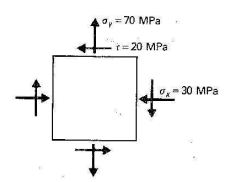
The figure shows the stresses at a point. Determine the principal stresses and the maximum shear stress. Show these values on the faces of properly oriented stress blocks.

Transcribed Image Text:+
0,= 70 MPa
-r=20 MPa
+
40
- 30 MPa
Expert Solution
This question has been solved!
Explore an expertly crafted, step-by-step solution for a thorough understanding of key concepts.
Step by stepSolved in 3 steps with 3 images

Knowledge Booster
Learn more about
Need a deep-dive on the concept behind this application? Look no further. Learn more about this topic, mechanical-engineering and related others by exploring similar questions and additional content below.Similar questions
- Determine (a) the principal stresses and (b) the maximum shear stress and associated normal stress at the point in Figure 4. Specify and sketch the orientation of the element in each case. The directions of the stress components are as indicated in Figure 4. 100 MPa 200 MPa 300 MPaarrow_forwardDetermine the equivalent state of stress on an element if it is oriented 30° clockwise from the element shown. Use the stress-transformation equations. 300 MPa 950 MParrow_forwardSolve shoe all steps and solitionarrow_forward
- For the element shown below, determine: 1- The principal stresses and the maximum in-plane shear stress acting at the point by using equations, then show these stresses on an appropriate sketch. 2- The normal stresses 0 n and ¢ t and the shear stress T nt for element oriented 20° clockwise from the position shown, using Mobhr’s Circle. 75 MPaarrow_forwardDetermine the average normal stress developed at points A, B, and C. The diameter of each segment is indicated in the figure.arrow_forwardAt a point in a strained material the principal stresses are 200 N/mm2 (tensile) and 120 N/mm2 (compressive). Determine the normal stress, shear stress and resultant stress on a plane inclined at 30° to the axis of major principal stress. Also determine the maximum shear stress at the point.arrow_forward
- Determine the equivalent state of stress which represents the principal stresses, and the maximum in-plane shear stress and the associated average normal stress. For each case, determine the corresponding orientation of the element with respect to the element shown in the figure below. (Figure 1) Determine the orientation of principal planes of stress. Express your answers in degrees to three significant figures separated by a comma.arrow_forwardConsider a point in a structural member that is subjected to plane stress. Normal and shear stress magnitudes acting on horizontal and vertical planes at the point are S, 2750 psi, S, = 1100 psi, and Sy 1950 psi. Assume ß - 53°. (a) Draw Mohr's circle for this state of stress. %3D (b) Determine the principal stresses and the maximum in-plane shear stress acting at the point. Show these stresses on an appropriate sketch (e.g., see Fig. 12.15 or Fig. 12.16). (c) Determine the normal and shear stresses on the indicated plane and show these stresses on a sketch. (d) Determine the absolute maximum shear stress at the point. Sxy Answer: (a) Draw Mohr's Circle for this state of stress. (b) op1- psi Op2 - psi Tmax in-plane psi (c) on psi Tnt psi (d) Tabs max psi eTextbook and Mediaarrow_forwardFor the shaft shown below, determine the normal and shear stresses acting on the element located at point A, including stress concentrations. Then draw the stress element at A with the applied stresses and determine the three principal stress (0₁, 2 and, σ3) using Mohr's circle. r = 0.0042 m, d = 0.03 m, D = 0.033 m, T = 250 Nm P = 1500 N, M = 300 Nm, A M M DEHRƏC T d T P P rarrow_forward
- The stresses shown below act on horizontal and vertical planes through a point on the surface of a stressed body. Determine and show on a sketch the principal stresses and the maximum shear stress at this point. 50 MPa -30 MPa 35 MPaarrow_forwardanswer this ; The von Mises equivalent stresses at point H can be calculated as MPaarrow_forwardUse Mohrs circle to find the principle stresses and determine the normal and shear stresses acting on a plane 45 degrees counter clockwise from the Y-plane. Sketch showing the exterior stresses.arrow_forward
arrow_back_ios
SEE MORE QUESTIONS
arrow_forward_ios
Recommended textbooks for you
 Elements Of ElectromagneticsMechanical EngineeringISBN:9780190698614Author:Sadiku, Matthew N. O.Publisher:Oxford University Press
 Mechanics of Materials (10th Edition)Mechanical EngineeringISBN:9780134319650Author:Russell C. HibbelerPublisher:PEARSON
 Thermodynamics: An Engineering ApproachMechanical EngineeringISBN:9781259822674Author:Yunus A. Cengel Dr., Michael A. BolesPublisher:McGraw-Hill Education
 Control Systems EngineeringMechanical EngineeringISBN:9781118170519Author:Norman S. NisePublisher:WILEY
 Mechanics of Materials (MindTap Course List)Mechanical EngineeringISBN:9781337093347Author:Barry J. Goodno, James M. GerePublisher:Cengage Learning
 Engineering Mechanics: StaticsMechanical EngineeringISBN:9781118807330Author:James L. Meriam, L. G. Kraige, J. N. BoltonPublisher:WILEY

Elements Of Electromagnetics
Mechanical Engineering
ISBN:9780190698614
Author:Sadiku, Matthew N. O.
Publisher:Oxford University Press

Mechanics of Materials (10th Edition)
Mechanical Engineering
ISBN:9780134319650
Author:Russell C. Hibbeler
Publisher:PEARSON

Thermodynamics: An Engineering Approach
Mechanical Engineering
ISBN:9781259822674
Author:Yunus A. Cengel Dr., Michael A. Boles
Publisher:McGraw-Hill Education

Control Systems Engineering
Mechanical Engineering
ISBN:9781118170519
Author:Norman S. Nise
Publisher:WILEY

Mechanics of Materials (MindTap Course List)
Mechanical Engineering
ISBN:9781337093347
Author:Barry J. Goodno, James M. Gere
Publisher:Cengage Learning

Engineering Mechanics: Statics
Mechanical Engineering
ISBN:9781118807330
Author:James L. Meriam, L. G. Kraige, J. N. Bolton
Publisher:WILEY