
Mechanics of Materials (10th Edition)
10th Edition
ISBN: 9780134319650
Author: Russell C. Hibbeler
Publisher: PEARSON
expand_more
expand_more
format_list_bulleted
Concept explainers
Videos
Textbook Question
Chapter 3.4, Problem 3.21P
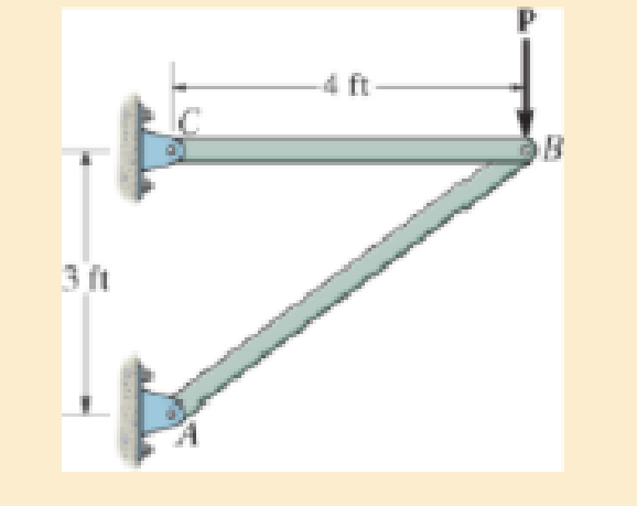
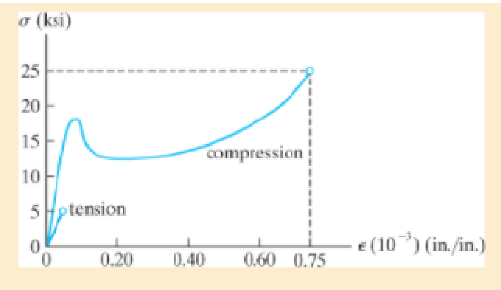
The two bars are made of a material that has the stress-strain diagram shown. If the cross-sectional area of bar AB is 1.5 in2 and BC is 4 in2, determine the largest force P that can be supported before any member fractures. Assume that buckling does not occur.
Expert Solution & Answer
Want to see the full answer?
Check out a sample textbook solution
Students have asked these similar questions
A 20-mm-wide block is firmly bonded to rigid plates at its top and bottom. When the force P is applied the block deforms into the shape shown by the dashed line. Determine the magnitude of P. The block’s material has a modulus of rigidity of G = 26 GPa. Assume that the material does not yield and use small-angle analysis.
Rod BD is made of steel (E = 29 × 106 psi) and is used to brace the axially compressed member ABC. The maximum force that can be developed in member BD is 0.02P. If the stress must not exceed 18 ksi and the maximum change in length of BD must not exceed 0.001 times the length of ABC, determine the smallest-diameter rod that can be used for member BD. Take P = 148 kips.The smallest-diameter rod that can be used for member BD is in.
Direct tension indicators are sometimes used instead of torque wrenches to ensure that a bolt has a prescribed tension when used for connections. If a nut on the bolt is tightened so that the six 3-mm high heads of the indicator are strained 0.1 mm>mm, and leave a contact area on each head of 1.5 mm2, determine the tension in the bolt shank. The material has the stress-straindiagram is shown.
Chapter 3 Solutions
Mechanics of Materials (10th Edition)
Ch. 3.4 - Define a homogeneous material.Ch. 3.4 - Indicate the points on the stress-strain diagram...Ch. 3.4 - Define the modulus of elasticity E.Ch. 3.4 - At room temperature, mild steel is a ductile...Ch. 3.4 - Engineering stress and strain are calculated using...Ch. 3.4 - As the temperature increases the modulus of...Ch. 3.4 - A 100-mm-long rod has a diameter of 15 mm. If an...Ch. 3.4 - A bar has a length of 8 in. and cross-sectional...Ch. 3.4 - A 10-mm-diameter rod has a modulus of elasticity...Ch. 3.4 - The material for the 50-mm-long specimen has the...
Ch. 3.4 - The material for the 50-mm-long specimen has the...Ch. 3.4 - If the elongation of wire BC is 0.2 mm after the...Ch. 3.4 - A tension test was performed on a steel specimen...Ch. 3.4 - Data taken from a stress-strain test for a ceramic...Ch. 3.4 - Data taken from a stress-strain test for a ceramic...Ch. 3.4 - The stress-strain diagram for a steel alloy having...Ch. 3.4 - The stress-strain diagram for a steel alloy having...Ch. 3.4 - The stress-strain diagram for a steel alloy having...Ch. 3.4 - The rigid beam is supported by a pin at C and an...Ch. 3.4 - The rigid beam is supported by a pin at C and an...Ch. 3.4 - Acetal plastic has a stress-strain diagram as...Ch. 3.4 - The stress-strain diagram for an aluminum alloy...Ch. 3.4 - The stress-strain diagram for an aluminum alloy...Ch. 3.4 - The stress-strain diagram for an aluminum alloy...Ch. 3.4 - A bar having a length of 5 in. and cross-sectional...Ch. 3.4 - The rigid pipe is supported by a pin at A and an...Ch. 3.4 - The rigid pipe is supported by a pin at A and an...Ch. 3.4 - Direct tension indicators are sometimes used...Ch. 3.4 - The rigid beam is supported by a pin at C and an...Ch. 3.4 - The rigid beam is supported by a pin at C and an...Ch. 3.4 - The stress-strain diagram for a bone is shown, and...Ch. 3.4 - The stress-strain diagram for a bone is shown and...Ch. 3.4 - The two bars are made of a material that has the...Ch. 3.4 - The two bars are made of a material that has the...Ch. 3.4 - The pole is supported by a pin at C and an A-36...Ch. 3.4 - The bar DA is rigid and is originally held in the...Ch. 3.7 - A 100-mm-long rod has a diameter of 15 mm. If an...Ch. 3.7 - A solid circular rod that is 600 mm long and 20 mm...Ch. 3.7 - A 20-mm-wide block is firmly bonded to rigid...Ch. 3.7 - A 20-mm-wide block is bonded to rigid plates at...Ch. 3.7 - The acrylic plastic rod is 200 mm long and 15 mm...Ch. 3.7 - The plug has a diameter of 30 mm and fits within a...Ch. 3.7 - The elastic portion of the stress-strain diagram...Ch. 3.7 - The elastic portion of the stress-strain diagram...Ch. 3.7 - The brake pads for a bicycle tire are made of...Ch. 3.7 - The lap joint is connected together using a 1.25...Ch. 3.7 - The lap joint is connected together using a 1.25...Ch. 3.7 - The rubber block is subjected to an elongation of...Ch. 3.7 - The shear stress-strain diagram for an alloy is...Ch. 3.7 - A shear spring is made from two blocks of rubber,...Ch. 3 - The elastic portion of the tension stress-strain...Ch. 3 - The elastic portion of the tension stress-strain...Ch. 3 - The rigid beam rests in the horizontal position on...Ch. 3 - The wires each have a diameter of 12 in., length...Ch. 3 - The wires each have a diameter of 12 in., length...Ch. 3 - diameter steel bolts. If the clamping force in...Ch. 3 - The stress-strain diagram for polyethylene, which...Ch. 3 - The pipe with two rigid caps attached to its ends...Ch. 3 - The 8-mm-diameter bolt is made of an aluminum...Ch. 3 - An acetal polymer block is fixed to the rigid...
Knowledge Booster


Learn more about
Need a deep-dive on the concept behind this application? Look no further. Learn more about this topic, mechanical-engineering and related others by exploring similar questions and additional content below.Similar questions
- 3. Direct tension indicators are sometimes used instead of torque wrenches to ensure that a bolt has a prescribed tension when used for connections. If a nut on the bolt is tightened so that the six 3-mm high heads of the indicator are strained 0.1 mm/mm, and leave a contact area on each head of 1.5 mm², determine the tension in the bolt shank. The stress-strain diagram of the indicator material (and bolt) is shown. 3 mm 1 σ (MPa) 600 450 0.0015 0.3 € (mm/mm)arrow_forwardThe rod is 200 mm long and 60 mm in diameter. If an axial load of 300 N is applied to it, determine the change in its length, the change in its diameter, normal stress and normal strain. The Poisson's ratio is 0.4 and the modulus of elasticity is 20 GPa.arrow_forwardThe rigid beam is supported by a pin at A and wires BD and CE. If the load P on the beam causes the end C to be displaced 15 mm downward, determineA. the normal strain developed in wire CEB. the normal strain developed in wires BD. Show free body diagram and complete solution (no shortcut) SHOW PRESSURE DIAGRAM. THANK YOUarrow_forward
- 8-18. The two bars are made of polystyrene, which has the stress-strain diagram shown. If the cross-sectional area of bar AB is 975 mm² and BC is 2600 mm?, determine the largest force P that can be supported before any member ruptures. Assume that buckling does not occur. 1m (MPa) 175 140 105 compression 70 35 H plension e (mm/mm) 0.20 0.40 0.60 0.80arrow_forwardA bar has a length of 200 mm and cross-sectional area of 7500 mm2. Determine the modulus ofelasticity of the material if it is subjected to an axial tensile load of 50 kN and stretches 0.075 mm.The material has linear-elastic behavior.arrow_forwardA 100-mm-long rod has a diameter of 15 mm. If an axial tensile load of 100 kN is applied, determine its change in length. Assume linear elastic behavior with E = 200 GPa.arrow_forward
- Two rods, A and B. of equal free length are elastic. Both hang vertically 0.6m apart and support a rigid bar horizontally. The bar remains horizontal when a vertical load of 60 KN is applied to the bar 0.2m from A. If the stress in A is 100 MPa, determine the stress in B and the cross-sectional areas of the two rods: Ea = 200 GPa, EB = 130 GPa.arrow_forwardB D The rods AB and CD are assumed to be pin connected at A and C. If the cable BD and CD are made of a material having of oy = 250 MPa 6 kN 5 kN 4 kN tensile stress determine the minimum diameter for cable AB and CD to avoid deformation. A C - 2 m–→--2 m–+ -3 m- -3 marrow_forwardThe elastic portion of the stress–strain diagram for an aluminum alloy is shown in the figure. The specimen from which it was obtained has an original diameter of 12.7 mm and a gage length of 50.8 mm. If a load of P = 60 kN is applied to the specimen, determine its new diameter and length. Taken = 0.35.arrow_forward
- 4. The rigid lever arm is supported by two A-36 steel wires having the same diameter of 4 mm. If a force of P = 3 kN is applied to the handle, determine the force developed in both wires and their corresponding elongations. Consider A-36 steel as an elastic-perfectly plastic material. 450 mm 150 mm 150 mm 30 A 300 mm B. Darrow_forwardA bar having a length of 5 in. and a cross-sectional area of 0.7 in.2 is subjected to an axial force of 8000 lb. If the bar stretches 0.002 in., determine the modulus of elasticity of the material. The material has linear elastic behavior.arrow_forwardThe rigid bar ABC pivots about support B. After application of load P, end C of the rigid bar moves upward by 0.07 in. If the length of bar (1) is L₁-41 in, determine the average normal strain in bar (1). Assume that a-135 in, b-39 in, and c-0.15 in a b C Rigid bar 4 Part 1 * Incorrect Determine the distance that end A of the rigid bar moves downward, if end C moves upward by 0.07 in Answer: in VA i 00361arrow_forward
arrow_back_ios
SEE MORE QUESTIONS
arrow_forward_ios
Recommended textbooks for you
 Elements Of ElectromagneticsMechanical EngineeringISBN:9780190698614Author:Sadiku, Matthew N. O.Publisher:Oxford University Press
 Mechanics of Materials (10th Edition)Mechanical EngineeringISBN:9780134319650Author:Russell C. HibbelerPublisher:PEARSON
 Thermodynamics: An Engineering ApproachMechanical EngineeringISBN:9781259822674Author:Yunus A. Cengel Dr., Michael A. BolesPublisher:McGraw-Hill Education
 Control Systems EngineeringMechanical EngineeringISBN:9781118170519Author:Norman S. NisePublisher:WILEY
 Mechanics of Materials (MindTap Course List)Mechanical EngineeringISBN:9781337093347Author:Barry J. Goodno, James M. GerePublisher:Cengage Learning
 Engineering Mechanics: StaticsMechanical EngineeringISBN:9781118807330Author:James L. Meriam, L. G. Kraige, J. N. BoltonPublisher:WILEY
Elements Of Electromagnetics
Mechanical Engineering
ISBN:9780190698614
Author:Sadiku, Matthew N. O.
Publisher:Oxford University Press
Mechanics of Materials (10th Edition)
Mechanical Engineering
ISBN:9780134319650
Author:Russell C. Hibbeler
Publisher:PEARSON
Thermodynamics: An Engineering Approach
Mechanical Engineering
ISBN:9781259822674
Author:Yunus A. Cengel Dr., Michael A. Boles
Publisher:McGraw-Hill Education
Control Systems Engineering
Mechanical Engineering
ISBN:9781118170519
Author:Norman S. Nise
Publisher:WILEY
Mechanics of Materials (MindTap Course List)
Mechanical Engineering
ISBN:9781337093347
Author:Barry J. Goodno, James M. Gere
Publisher:Cengage Learning
Engineering Mechanics: Statics
Mechanical Engineering
ISBN:9781118807330
Author:James L. Meriam, L. G. Kraige, J. N. Bolton
Publisher:WILEY
Stresses Due to Fluctuating Loads Introduction - Design Against Fluctuating Loads - Machine Design 1; Author: Ekeeda;https://www.youtube.com/watch?v=3FBmQXfP_eE;License: Standard Youtube License