
Mechanics of Materials (10th Edition)
10th Edition
ISBN: 9780134319650
Author: Russell C. Hibbeler
Publisher: PEARSON
expand_more
expand_more
format_list_bulleted
Videos
Textbook Question
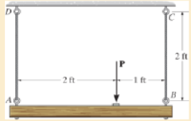
Chapter 3, Problem 3.5RP
The wires each have a diameter of
Expert Solution & Answer
Want to see the full answer?
Check out a sample textbook solution
Students have asked these similar questions
The assembly consists of three titanium (Ti-6A1-4V) rods and a rigid bar AC.
The image shows the cross-sectional area of the assembly
.If a force P= 66 kNkN is applied to the ring F, what isthe angle of tilt of bar AC measured counterclockwise from the negative y axis.
The 250-N block rests upon a level plane for which fk = 0.2. It is pulled by force P = 100N inclined at 20o with the horizontal. If the 100-N pull is then removed, find the distance the block will travel.
the answer must 3 decimal places.
The beam of negligible weight is supported horizontally by two springs. If the beam is horizontal and the springs are unstretched when the load is removed, determine the angle of tilt of the beam when the load is applied. Take x = 659 N/m, y = 1.5 kN/m, and z = 1.6 kN/m.
Chapter 3 Solutions
Mechanics of Materials (10th Edition)
Ch. 3.4 - Define a homogeneous material.Ch. 3.4 - Indicate the points on the stress-strain diagram...Ch. 3.4 - Define the modulus of elasticity E.Ch. 3.4 - At room temperature, mild steel is a ductile...Ch. 3.4 - Engineering stress and strain are calculated using...Ch. 3.4 - As the temperature increases the modulus of...Ch. 3.4 - A 100-mm-long rod has a diameter of 15 mm. If an...Ch. 3.4 - A bar has a length of 8 in. and cross-sectional...Ch. 3.4 - A 10-mm-diameter rod has a modulus of elasticity...Ch. 3.4 - The material for the 50-mm-long specimen has the...
Ch. 3.4 - The material for the 50-mm-long specimen has the...Ch. 3.4 - If the elongation of wire BC is 0.2 mm after the...Ch. 3.4 - A tension test was performed on a steel specimen...Ch. 3.4 - Data taken from a stress-strain test for a ceramic...Ch. 3.4 - Data taken from a stress-strain test for a ceramic...Ch. 3.4 - The stress-strain diagram for a steel alloy having...Ch. 3.4 - The stress-strain diagram for a steel alloy having...Ch. 3.4 - The stress-strain diagram for a steel alloy having...Ch. 3.4 - The rigid beam is supported by a pin at C and an...Ch. 3.4 - The rigid beam is supported by a pin at C and an...Ch. 3.4 - Acetal plastic has a stress-strain diagram as...Ch. 3.4 - The stress-strain diagram for an aluminum alloy...Ch. 3.4 - The stress-strain diagram for an aluminum alloy...Ch. 3.4 - The stress-strain diagram for an aluminum alloy...Ch. 3.4 - A bar having a length of 5 in. and cross-sectional...Ch. 3.4 - The rigid pipe is supported by a pin at A and an...Ch. 3.4 - The rigid pipe is supported by a pin at A and an...Ch. 3.4 - Direct tension indicators are sometimes used...Ch. 3.4 - The rigid beam is supported by a pin at C and an...Ch. 3.4 - The rigid beam is supported by a pin at C and an...Ch. 3.4 - The stress-strain diagram for a bone is shown, and...Ch. 3.4 - The stress-strain diagram for a bone is shown and...Ch. 3.4 - The two bars are made of a material that has the...Ch. 3.4 - The two bars are made of a material that has the...Ch. 3.4 - The pole is supported by a pin at C and an A-36...Ch. 3.4 - The bar DA is rigid and is originally held in the...Ch. 3.7 - A 100-mm-long rod has a diameter of 15 mm. If an...Ch. 3.7 - A solid circular rod that is 600 mm long and 20 mm...Ch. 3.7 - A 20-mm-wide block is firmly bonded to rigid...Ch. 3.7 - A 20-mm-wide block is bonded to rigid plates at...Ch. 3.7 - The acrylic plastic rod is 200 mm long and 15 mm...Ch. 3.7 - The plug has a diameter of 30 mm and fits within a...Ch. 3.7 - The elastic portion of the stress-strain diagram...Ch. 3.7 - The elastic portion of the stress-strain diagram...Ch. 3.7 - The brake pads for a bicycle tire are made of...Ch. 3.7 - The lap joint is connected together using a 1.25...Ch. 3.7 - The lap joint is connected together using a 1.25...Ch. 3.7 - The rubber block is subjected to an elongation of...Ch. 3.7 - The shear stress-strain diagram for an alloy is...Ch. 3.7 - A shear spring is made from two blocks of rubber,...Ch. 3 - The elastic portion of the tension stress-strain...Ch. 3 - The elastic portion of the tension stress-strain...Ch. 3 - The rigid beam rests in the horizontal position on...Ch. 3 - The wires each have a diameter of 12 in., length...Ch. 3 - The wires each have a diameter of 12 in., length...Ch. 3 - diameter steel bolts. If the clamping force in...Ch. 3 - The stress-strain diagram for polyethylene, which...Ch. 3 - The pipe with two rigid caps attached to its ends...Ch. 3 - The 8-mm-diameter bolt is made of an aluminum...Ch. 3 - An acetal polymer block is fixed to the rigid...
Knowledge Booster


Learn more about
Need a deep-dive on the concept behind this application? Look no further. Learn more about this topic, mechanical-engineering and related others by exploring similar questions and additional content below.Similar questions
- Solve Prob. 7.29 if =0.arrow_forwardDetermine the magnitude and direction with respect to the +x axis on the reaction at A and at C. Note that the body is supported by pin at A and a roller at C. The body's weight is negligible. 2.4 kN-m 400 40° 200 250 Dimensions in mm -300- B 3 kNarrow_forwardThe steel strip has a uniform thickness of 50 mm. Compute the elongation of the strip caused by the 500-kN axial force. The modulus of elasticity of steel is 200 GPa.arrow_forward
- Determine the maximum moment (k-ft) at the given structure. Support A is fixed, joint B is a pin and support C is roller. 20 k 0.5 k/ft B 8 ft 6 ft 6 ftarrow_forwardIf the maximum resisting moment at point A is 150 N.m about the x-axis. Determine the largest magnitude of force F that can be applied to the member so that the member will not turn. 45° 60" Be 60° l100 mm 150 mm 350 mmarrow_forwardDetermine the distance that end A of the rigid bar moves downward, if end C moves upward by 0.06 in.arrow_forward
- 1-1 Determine the resultant internal normal force acting on the cross section through point A in each column. In (a), segment BC weighs 180 lb/ft and segment CD weighs 250 lb/ft. In (b), the column has a mass of 200 kg/m. 5 kip |8 kN B 200 mm 200 mm 6 kN| 6 kN 10 ft 8 in. 3 m 8 in. 200 mm 200 mm 3 kip 3 kip 4.5 kN 14.5 kN C 4 ft A A 4 ft I m D (а) (h)arrow_forwardThe rigid bar AB and CD are supported by pins at A and D. the vertical rods are made of aluminum and bronze. Determine the vertical displacement of the point where the force P= 10 kips is applied. Neglect the weight of the members.arrow_forwardQ12/ Determine the resultant R of the three tension forces acting on the eye bolt. Find the magnitude of R and the angle 0 which R makes with positive x-axis? Ans: R = 17.82 N, 0= 26.1 20 kN 45 8 kN 4 kNarrow_forward
- The force P is applied to the bar, which is made from an elastic perfectly plastic material. Construct a graph to show how the force in each section AB and BC (vertical axis) varies as P (horizontal axis) is increased. The bar has cross-sectional areas of 1 in2 in region AB and 4 in2 in region BC. Take sY = 30 ksi.arrow_forwardPlease determine the change in diameter of the bar ass well as the change in lenght of the bar, if the bar is subjected to axial force of 160 KNarrow_forwardThe wall-mounted 3kg light fixture has its mass centre at G. Determine the vector reactions at A. -10 mm 100 mm 200 mm 230 mm If this vector reaction force can be written as R, = Ri + Rmj, in newtons, determine the components of the reaction force R and R- Choose.. + Rby Choose... Rhzarrow_forward
arrow_back_ios
SEE MORE QUESTIONS
arrow_forward_ios
Recommended textbooks for you
 International Edition---engineering Mechanics: St...Mechanical EngineeringISBN:9781305501607Author:Andrew Pytel And Jaan KiusalaasPublisher:CENGAGE L
International Edition---engineering Mechanics: St...
Mechanical Engineering
ISBN:9781305501607
Author:Andrew Pytel And Jaan Kiusalaas
Publisher:CENGAGE L
Mechanics of Materials Lecture: Beam Design; Author: UWMC Engineering;https://www.youtube.com/watch?v=-wVs5pvQPm4;License: Standard Youtube License