
VECTOR MECHANICS FOR ENGINEERS: STATICS
12th Edition
ISBN: 9781259977121
Author: BEER
Publisher: MCG
expand_more
expand_more
format_list_bulleted
Concept explainers
Videos
Textbook Question
Chapter 3.3, Problem 3.73P
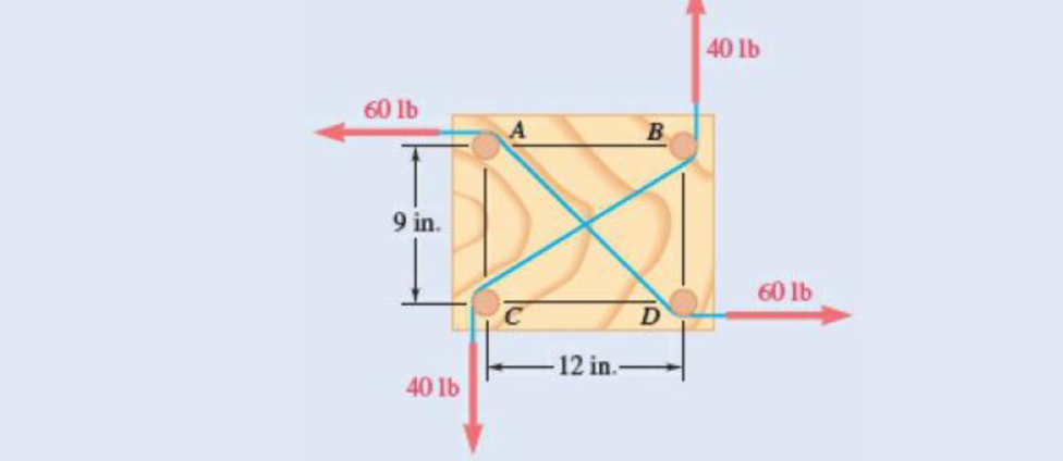
Four pegs of the same diameter are attached to a board as shown. Two strings are passed around the pegs and pulled with the forces indicated. Determine the diameter of the pegs knowing that the resultant couple applied to the board is 1132.5 lb·in. counterclockwise.
Expert Solution & Answer
Want to see the full answer?
Check out a sample textbook solution
Students have asked these similar questions
a 300n girl and an 400n boy stand on a 16m platform supported by posts A and B. The platform itself weighs 200N. What are the forces exerted by the supports on the platform?
C
A cylindrical piece of steel 38 mm (1½ in.) in
diameter is to be quenched in moderately agi-
tated oil. Surface and center hardnesses must be
at least 50 and 40 HRC, respectively. Which of
the following alloys satisfy these requirements:
1040, 5140, 4340, 4140, and 8640? Justify your
choice(s).
Using the isothermal transformation diagram for a 1.13 wt% C steel alloy (Figure 10.39),
determine the final microstructure (in terms of just the microconstituents present) of a small
specimen that has been subjected to the following time-temperature treatments. In each case
assume that the specimen begins at 920°C (1690°F) and that it has been held at this
temperature long enough to have achieved a complete and homogeneous austenitic structure.
(a) Rapidly cool to 250°C (480°F), hold for 103 s, then quench to room temperature.
(b) Rapidly cool to 775°C (1430°F), hold for 500 s, then quench to room temperature.
(c) Rapidly cool to 400°C (750°F), hold for 500 s, then quench to room temperature.
(d) Rapidly cool to 700°C (1290°F), hold at this temperature for 105 s, then quench to room
temperature.
(e) Rapidly cool to 650°C (1200°F), hold at this temperature for 3 s, rapidly cool to 400°C
(750°F), hold for 25 s, then quench to room temperature.
(f) Rapidly cool to 350°C (660°F), hold for…
Chapter 3 Solutions
VECTOR MECHANICS FOR ENGINEERS: STATICS
Ch. 3.1 - A foot valve for a pneumatic system is hinged at...Ch. 3.1 - 3.2A foot valve for a pneumatic system is hinged...Ch. 3.1 - It is known that a vertical force of 200 lb is...Ch. 3.1 - A 300-N force is applied at A as shown. Determine...Ch. 3.1 - A 300-N force is applied at A as shown. Determine...Ch. 3.1 - An 8-lb force P is applied to a shift lever....Ch. 3.1 - Prob. 3.7PCh. 3.1 - An 11-lb force P is applied to a shift lever. The...Ch. 3.1 - Rod AB is held in place by the cord AC. Knowing...Ch. 3.1 - Rod AB is held in place by the cord AC. Knowing...
Ch. 3.1 - 3.11 and 3.12The tailgate of a car is supported by...Ch. 3.1 - 3.11 and 3.12The tailgate of a car is supported by...Ch. 3.1 - 3.13 and 3.14It is known that the connecting rod...Ch. 3.1 - 3.13 and 3.14It is known that the connecting rod...Ch. 3.1 - Form the vector product P1 P2 and use the result...Ch. 3.1 - The vectors P and Q are two adjacent sides of a...Ch. 3.1 - Prob. 3.17PCh. 3.1 - Prob. 3.18PCh. 3.1 - Prob. 3.19PCh. 3.1 - Prob. 3.20PCh. 3.1 - Before the trunk of a large tree is felled, cables...Ch. 3.1 - The 12-ft boom AB has a fixed end A. A steel cable...Ch. 3.1 - A 200-N force is applied as shown to the bracket...Ch. 3.1 - A force P of magnitude 200 N acts along the...Ch. 3.1 - A 6-ft-long fishing rod AB is securely anchored in...Ch. 3.1 - A precast concrete wall section is temporarily...Ch. 3.1 - In Prob. 3.22, determine the perpendicular...Ch. 3.1 - In Prob. 3.23, determine the perpendicular...Ch. 3.1 - In Prob. 3.24, determine the perpendicular...Ch. 3.1 - In Prob. 3.25, determine the perpendicular...Ch. 3.1 - In Prob. 3.25, determine the perpendicular...Ch. 3.1 - In Prob. 3.26, determine the perpendicular...Ch. 3.1 - In Prob. 3.26, determine the perpendicular...Ch. 3.1 - Determine the value of a that minimizes the...Ch. 3.2 - Given the vectors P = 2i + j + 2k, Q = 3i + 4j ...Ch. 3.2 - Form the scalar product B C and use the result...Ch. 3.2 - Three cables are attached to the top of the tower...Ch. 3.2 - Prob. 3.38PCh. 3.2 - Knowing that the tension in cable AC is 280 lb,...Ch. 3.2 - Knowing that the tension in cable AD is 180 lb,...Ch. 3.2 - Ropes AB and BC are two of the ropes used to...Ch. 3.2 - Ropes AB and BC are two of the ropes used to...Ch. 3.2 - The 20-in. tube AB can slide along a horizontal...Ch. 3.2 - Solve Prob. 3.43 for the position corresponding to...Ch. 3.2 - Determine the volume of the parallelepiped of Fig....Ch. 3.2 - Prob. 3.46PCh. 3.2 - A crane is oriented so that the end of the 25-m...Ch. 3.2 - 3.48The 25-m crane boom AO lies in the yz plane....Ch. 3.2 - To loosen a frozen valve, a force F with a...Ch. 3.2 - 3.50When a force F is applied to the handle of the...Ch. 3.2 - The 0.61 1.00-m lid ABCD of a storage bin is...Ch. 3.2 - Prob. 3.52PCh. 3.2 - A farmer uses cables and winch pullers B and E to...Ch. 3.2 - Solve Prob. 3.53 when the tension in cable AB is...Ch. 3.2 - A force P of magnitude 520 lb acts on the frame...Ch. 3.2 - 3.56A force P acts on the frame shown at point E....Ch. 3.2 - The frame ACD is hinged at A and D and is...Ch. 3.2 - In Prob. 3.57, determine the moment about the...Ch. 3.2 - The triangular plate ABC is supported by...Ch. 3.2 - 3.60The triangular plate ABC is supported by...Ch. 3.2 - Prob. 3.61PCh. 3.2 - Prob. 3.62PCh. 3.2 - Two forces F1 and F2 in space have the same...Ch. 3.2 - Prob. 3.64PCh. 3.2 - Prob. 3.65PCh. 3.2 - In Prob. 3.57, determine the perpendicular...Ch. 3.2 - In Prob. 3.58, determine the perpendicular...Ch. 3.2 - In Prob. 3.59, determine the perpendicular...Ch. 3.2 - In Prob. 3.60, determine the perpendicular...Ch. 3.3 - Two 80-N forces are applied as shown to the...Ch. 3.3 - Two parallel 60-N forces are applied as shown to...Ch. 3.3 - A multiple-drilling machine is used to drill...Ch. 3.3 - Four pegs of the same diameter are attached to a...Ch. 3.3 - A piece of plywood in which several holes are...Ch. 3.3 - The shafts of an angle drive are acted upon by the...Ch. 3.3 - Prob. 3.76PCh. 3.3 - 3.77If P = 20 lb in the figure, replace the three...Ch. 3.3 - The two couples shown are to be replaced with a...Ch. 3.3 - Solve part a of Prob. 3.78, assuming that two 15-N...Ch. 3.3 - Shafts A and B connect the gear box to the wheel...Ch. 3.3 - A 500-N force is applied to a bent plate as shown....Ch. 3.3 - A crane column supports a 16-kip load as shown....Ch. 3.3 - A dirigible is tethered by a cable attached to its...Ch. 3.3 - A 30-lb vertical force P is applied at A to the...Ch. 3.3 - A worker tries to move a rock by applying a 360-N...Ch. 3.3 - A worker tries to move a rock by applying a 360-N...Ch. 3.3 - The shearing forces exerted on the cross section...Ch. 3.3 - Knowing that = 60, replace the force and couple...Ch. 3.3 - Three control rods attached to a lever ABC exert...Ch. 3.3 - A rectangular plate is acted upon by the force and...Ch. 3.3 - While tapping a hole, a machinist applies the...Ch. 3.3 - A hexagonal plate is acted upon by the force P and...Ch. 3.3 - Replace the 250-kN force P with an equivalent...Ch. 3.3 - A 2.6-kip force is applied at point D of the...Ch. 3.3 - Replace the 150-N force with an equivalent...Ch. 3.3 - To keep a door closed, a wooden stick is wedged...Ch. 3.3 - A 46-lb force F and a 2120-lbin. couple M are...Ch. 3.3 - A 110-N force acting in a vertical plane parallel...Ch. 3.3 - The 12-ft boom AB has a fixed end A, and the...Ch. 3.3 - The jib crane shown is oriented so that its boom...Ch. 3.4 - 3.101A 4-m-long beam is subjected to a variety of...Ch. 3.4 - Prob. 3.102PCh. 3.4 - Determine the single equivalent force and the...Ch. 3.4 - Five separate force-couple systems act at the...Ch. 3.4 - The weights of two children sitting at ends A and...Ch. 3.4 - Three stage lights are mounted on a pipe as shown....Ch. 3.4 - A beam supports three loads of given magnitude and...Ch. 3.4 - A 6 12-in. plate is subjected to four loads as...Ch. 3.4 - Gear C is rigidly attached to arm AB. If the...Ch. 3.4 - To test the strength of a 625 500-mm suitcase,...Ch. 3.4 - Two cables exert forces of 90 kN each on a truss...Ch. 3.4 - Pulleys A and B are mounted on bracket CDEF. The...Ch. 3.4 - The roof of a building frame is subjected to the...Ch. 3.4 - A couple of magnitude M = 80 lbin. and the three...Ch. 3.4 - A couple M and the three forces shown are applied...Ch. 3.4 - A machine component is subjected to the forces and...Ch. 3.4 - Solve Prob. 3.116, assuming that P = 60 N.Ch. 3.4 - As follower AB rolls along the surface of member...Ch. 3.4 - A machine component is subjected to the forces...Ch. 3.4 - Two 150-mm-diameter pulleys are mounted on line...Ch. 3.4 - As an adjustable brace BC is used to bring a wall...Ch. 3.4 - In order to unscrew the tapped faucet A, a plumber...Ch. 3.4 - Assuming = 60 in Prob. 3.122, replace the two...Ch. 3.4 - Four forces are applied to the machine component...Ch. 3.4 - A blade held in a brace is used to tighten a screw...Ch. 3.4 - A mechanic uses a crowfoot wrench to loosen a bolt...Ch. 3.4 - Prob. 3.127PCh. 3.4 - Prob. 3.128PCh. 3.4 - Four signs are mounted on a frame spanning a...Ch. 3.4 - Prob. 3.130PCh. 3.4 - A concrete foundation mat of 5-m radius supports...Ch. 3.4 - Determine the magnitude and the point of...Ch. 3.4 - Prob. 3.133PCh. 3.4 - A piece of sheet metal is bent into the shape...Ch. 3.4 - Prob. 3.135PCh. 3.4 - Prob. 3.136PCh. 3.4 - Two bolts at A and B are tightened by applying the...Ch. 3.4 - Two bolts at A and B are tightened by applying the...Ch. 3.4 - Prob. 3.139PCh. 3.4 - A flagpole is guyed by three cables. If the...Ch. 3.4 - 3.141 and 3.142Determine whether the...Ch. 3.4 - 3.141 and 3.142Determine whether the...Ch. 3.4 - Replace the wrench shown with an equivalent system...Ch. 3.4 - Show that, in general, a wrench can be replaced...Ch. 3.4 - Show that a wrench can be replaced with two...Ch. 3.4 - Show that a wrench can be replaced with two...Ch. 3 - A 300-N force P is applied at point A of the bell...Ch. 3 - A winch puller AB is used to straighten a fence...Ch. 3 - A small boat hangs from two davits, one of which...Ch. 3 - Prob. 3.150RPCh. 3 - A single force P acts at C in a direction...Ch. 3 - The 23-in. vertical rod CD is welded to the...Ch. 3 - In a manufacturing operation, three holes are...Ch. 3 - A 260-lb force is applied at A to the rolled-steel...Ch. 3 - Prob. 3.155RPCh. 3 - A 77-N force F1 and a 31-Nm couple M1 are applied...Ch. 3 - Three horizontal forces are applied as shown to a...Ch. 3 - While using a pencil sharpener, a student applies...
Knowledge Booster


Learn more about
Need a deep-dive on the concept behind this application? Look no further. Learn more about this topic, mechanical-engineering and related others by exploring similar questions and additional content below.Similar questions
- How to solve this?arrow_forwardA start-up company wants to convert an ICE vehicle into an electric vehicle with the following specification. Power: 250 (HP) horsepower, (note: 1HP = 745 W) Range: 300-miles Fuel economy: 33.5 kilometers per gallon of gasoline. Efficiency of the ICE: 25% Energy Conversion: One gallon of gasoline at 100% efficiency is equal to 33.5 kWh/gallon). a)Calculate the EV consumption rate as Wh/km and find the total energy of the battery pack in KWh to replace the internal combustion engine. b)Design an 8-module battery pack for this full electric vehicle without compromising its range and performance (power). Use commercially available cylindrical cells lithium cell with 20Ah capacity and 3.125 V average voltage. Cell dimensions are 5cm diameter and 10 cm height. The electric motor requires 250 V input that will be provided directly from the battery pack, Report the configuration of each module in…arrow_forward"11-17 The shaft shown in Figure P11-3 was designed in Problem 10-17. For the data in the row(s) assigned from Table P11-1, and the corresponding diameter of shaft found in Problem 10-17, design suitable bearings to support the load for at least 1E8 cycles at 1800 rpm. State all assumptions. (a) Using hydrodynamically lubricated bronze sleeve bearings with Ox = 15, 11d=0.75, and a clearance ratio of 0.001. ✓ ✓ cast-iron roller FIGURE P11-3 Shaft Design for Problems 11-17 b gear key assume bearings act as simple supports 11-19 The shaft shown in Figure P11-4 was designed in Problem 10-19. For the data in the row(s) assigned from Table P11-1, and the corresponding diameter of shaft found in Problem 10-19, design suitable bearings to support the load for at least 5E8 cycles at 1200 rpm. State all assumptions. (a) Using hydrodynamically lubricated bronze sleeve bearings with Oy = 40, 1/d=0.80, and a clearance ratio of 0.002 5. gear gear key FIGURE P11-4 Shaft Design for Problems 11-19 and…arrow_forward
- For the frame below calculate the bending moment at point R. Take P=40 and note that this value is used for both the loads and the lengths of the members of the frame. 2.5P- A Q B R С 45 degrees ✗ ✗ P i 19 Кур -2P- 4PRN -P- -arrow_forwardCalculate the bending moment at the point D on the beam below. Take F=79 and remember that this quantity is to be used to calculate both forces and lengths. 15F 30F A сarrow_forwardShow work on how to obtain P2 and T2. If using any table, please refer to it. If applying interpolation method, please show the work.arrow_forward
- cast-iron roller FIGURE P11-3 Shaft Design for Problems 11-17 Chapter 11 BEARINGS AND LUBRICATION 677 gear key P assume bearings act as simple supports 11-18 Problem 7-18 determined the half-width of the contact patch for a 1.575-in-dia steel cylinder, 9.843 in long, rolled against a flat aluminum plate with 900 lb of force to be 0.0064 in. If the cylinder rolls at 800 rpm, determine its lubrication condition with ISO VG 1000 oil at 200°F. R₁ = 64 μin (cylinder); R₁ = 32 μin (plate). 11-19 The shaft shown in Figure P11-4 was designed in Problem 10-19. For the data in the row(s) assigned from Table P11-1, and the corresponding diameter of shaft found in Problem 10-19, design suitable bearings to support the load for at least 5E8 cycles at 1200 rpm. State all assumptions. (a) (b) Using hydrodynamically lubricated bronze sleeve bearings with ON = 40, 1/ d=0.80, and a clearance ratio of 0.002 5. Using deep-groove ball bearings for a 10% failure rate. *11-20 Problem 7-20 determined the…arrow_forwardCalculate the shear force at the point D on the beam below. Take F=19 and remember that this quantity is to be used to calculate both forces and lengths. 15F A сarrow_forward"II-1 The shaft shown in Figure P11-I was designed in Problem 10-1. For the data in the row(s) assigned from Table P11-1, and the corresponding diameter of shaft found in Problem 10-1, design suitable bearings to support the load for at least 7E7 cycles at 1500 rpm. State all assumptions. (a) Using hydrodynamically lubricated bronze sleeve bearings with Ox = 20, 1/d=1.25, and a clearance ratio of 0.001 5. assume bearings act as simple supports FIGURE P11-1 Shaft Design for Problem 11-1 11-2 The shaft shown in Figure P11-2 was designed in Problem 10-2. For the data in the row(s) assigned from Table P11-1, and the corresponding diameter of shaft found in Problem 10-2, design suitable bearings to support the load for at least 3E8 cycles at 2.500 rpm. State all assumptions. (a) Using hydrodynamically lubricated bronze sleeve bearings with ON=30, 1/d=1.0, and a clearance ratio of 0.002. FIGURE P11-2 Shaft Design for Problem 11-2 Table P11-1 Data for Problems assume bearings act as simple…arrow_forward
- For the frame below, calculate the shear force at point Q. Take P=13 and note that this value is used for both the loads and the lengths of the members of the frame. 1 A Q ✗ 19 KBP 2.5P- B R C 45 degrees ✗ 1 .2P- 4PhN -P→arrow_forwardCalculate the Bending Moment at point D in the frame below. Leave your answer in Nm (newton-metres) J J A 2m 2m <2m х D 不 1m X E 5m 325 Nm 4x 400N/marrow_forwardIn the beam below, calculate the shear force at point A. Take L=78 and remember that both the loads and the dimensions are expressed in terms of L. 143 1 DX A - Li 4 LhN 14LRN/m Х B 22 3 L.arrow_forward
arrow_back_ios
SEE MORE QUESTIONS
arrow_forward_ios
Recommended textbooks for you
 International Edition---engineering Mechanics: St...Mechanical EngineeringISBN:9781305501607Author:Andrew Pytel And Jaan KiusalaasPublisher:CENGAGE L
International Edition---engineering Mechanics: St...
Mechanical Engineering
ISBN:9781305501607
Author:Andrew Pytel And Jaan Kiusalaas
Publisher:CENGAGE L
Introduction To Engg Mechanics - Newton's Laws of motion - Kinetics - Kinematics; Author: EzEd Channel;https://www.youtube.com/watch?v=ksmsp9OzAsI;License: Standard YouTube License, CC-BY