
Videos
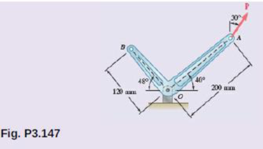
A 300-N force P is applied at point A of the bell crank shown. (a) Compute the moment of the force P about O by resolving it into horizontal and vertical components. (b) Using the result of part a, determine the perpendicular distance from O to the line of action of P.
(a)
The moment of the force P about O
Answer to Problem 3.147RP
The magnitude of the moment is about O is 20.5 N⋅m_.
Explanation of Solution
The magnitude of P is 300 N.
Write the expression for the vector from O to A.
rOA=200 mm(1 m1000 mm)cos40° ˆi+200 mm(1 m1000 mm)sin40° ˆj=(0.153209 ˆi+0.128558 ˆj) m (I)
Here rOA is the vector from O to A.
Write the expression for the force vector F.
F=300 N(sin30°) ˆi+300 N(cos30°) ˆj=(150 N) ˆi+(259.81 N) ˆj (II)
Write the expression for the moment at O.
MO=(rOA×F)
Here MO is the moment at O.
Conclusion:
Substitute (I) and (II) in the above equation to calculate MO.
MO=(0.153209 ˆi+0.128558 ˆj) m×(150 N ˆi+259.81 N ˆj)=(39.805 ˆk−19.2837 ˆk) N⋅m=(20.521 N⋅m) ˆk=20.5 N⋅m
Thus, the magnitude of moment at O is 20.5 N⋅m_.
(b)
The perpendicular distance from the point O to P.
Answer to Problem 3.147RP
The perpendicular distance from the point O to P is 68.3 mm_.
Explanation of Solution
The magnitude of moment at O is 20.5 N⋅m.
Write the expression to calculate the perpendicular distance from the point O to force P.
Fd=MO
Here d is the perpendicular distance, F is the magnitude of force P and MO is the magnitude of the moment.
Conclusion:
Substitute 300 N for P and 20.5 N⋅m for MO in the above equation to calculate d.
(300 N)d=20.5 N⋅md=20.5 N⋅m300 N=0.0683 m(1000 mm1 m)=68.3 mm
Thus, the perpendicular distance from the point O to P is 68.3 mm_.
Want to see more full solutions like this?
Chapter 3 Solutions
VECTOR MECHANICS FOR ENGINEERS: STATICS


- Calculate the bending moment at the point D on the beam below. Take F=79 and remember that this quantity is to be used to calculate both forces and lengths. 15F 30F A сarrow_forwardShow work on how to obtain P2 and T2. If using any table, please refer to it. If applying interpolation method, please show the work.arrow_forwardcast-iron roller FIGURE P11-3 Shaft Design for Problems 11-17 Chapter 11 BEARINGS AND LUBRICATION 677 gear key P assume bearings act as simple supports 11-18 Problem 7-18 determined the half-width of the contact patch for a 1.575-in-dia steel cylinder, 9.843 in long, rolled against a flat aluminum plate with 900 lb of force to be 0.0064 in. If the cylinder rolls at 800 rpm, determine its lubrication condition with ISO VG 1000 oil at 200°F. R₁ = 64 μin (cylinder); R₁ = 32 μin (plate). 11-19 The shaft shown in Figure P11-4 was designed in Problem 10-19. For the data in the row(s) assigned from Table P11-1, and the corresponding diameter of shaft found in Problem 10-19, design suitable bearings to support the load for at least 5E8 cycles at 1200 rpm. State all assumptions. (a) (b) Using hydrodynamically lubricated bronze sleeve bearings with ON = 40, 1/ d=0.80, and a clearance ratio of 0.002 5. Using deep-groove ball bearings for a 10% failure rate. *11-20 Problem 7-20 determined the…arrow_forward
- Calculate the shear force at the point D on the beam below. Take F=19 and remember that this quantity is to be used to calculate both forces and lengths. 15F A сarrow_forward"II-1 The shaft shown in Figure P11-I was designed in Problem 10-1. For the data in the row(s) assigned from Table P11-1, and the corresponding diameter of shaft found in Problem 10-1, design suitable bearings to support the load for at least 7E7 cycles at 1500 rpm. State all assumptions. (a) Using hydrodynamically lubricated bronze sleeve bearings with Ox = 20, 1/d=1.25, and a clearance ratio of 0.001 5. assume bearings act as simple supports FIGURE P11-1 Shaft Design for Problem 11-1 11-2 The shaft shown in Figure P11-2 was designed in Problem 10-2. For the data in the row(s) assigned from Table P11-1, and the corresponding diameter of shaft found in Problem 10-2, design suitable bearings to support the load for at least 3E8 cycles at 2.500 rpm. State all assumptions. (a) Using hydrodynamically lubricated bronze sleeve bearings with ON=30, 1/d=1.0, and a clearance ratio of 0.002. FIGURE P11-2 Shaft Design for Problem 11-2 Table P11-1 Data for Problems assume bearings act as simple…arrow_forwardFor the frame below, calculate the shear force at point Q. Take P=13 and note that this value is used for both the loads and the lengths of the members of the frame. 1 A Q ✗ 19 KBP 2.5P- B R C 45 degrees ✗ 1 .2P- 4PhN -P→arrow_forward
- Calculate the Bending Moment at point D in the frame below. Leave your answer in Nm (newton-metres) J J A 2m 2m <2m х D 不 1m X E 5m 325 Nm 4x 400N/marrow_forwardIn the beam below, calculate the shear force at point A. Take L=78 and remember that both the loads and the dimensions are expressed in terms of L. 143 1 DX A - Li 4 LhN 14LRN/m Х B 22 3 L.arrow_forwardCalculate the Shear Force at Point F on the beam below. Keep your answer in Newtons and make shear force positive to the right. A х 2m <2m E D 5m 1m Хт 325N1m 400N/m 8arrow_forward
- The normal force at C on the beam below is equal to: A ShN C X 15h N 8 ○ OkN 2.5kN 10kN ○ 12.5kN 1m Im 1m 1m;arrow_forwardCalculate the y coordinate of the of the centroid of the shape below. Take A= 18.5 8 6A 4A X 6Aarrow_forwardIn MATLAB write out a program to integrate the equations of motion of a rigid body. The inertia matrix is given by I = [125 0 0; 0 100 0; 0 0 75] which is a diagonal, where diag operator provides a matrix with given elements placed on its diagonal. Consider three cases where the body rotates 1 rad/sec about each principal axis. Integrate the resulting motion and study the angular rates and the resulting attitude (use any attitude coordinates). For each principal axis case, assume first that a pure spin about the principal axis is performed, and then repeat the simulation where a small 0.1 rad/sec motion is present about another principal axis. Discuss the stability of each motion. The code should produce a total of 6 simulations results when it is ran.arrow_forward
 International Edition---engineering Mechanics: St...Mechanical EngineeringISBN:9781305501607Author:Andrew Pytel And Jaan KiusalaasPublisher:CENGAGE L