
Concept explainers
(a)
The emf across
(a)
Answer to Problem 52CP
The emf across
Explanation of Solution
Given info: The battery emf is
Initially switch s is closed so the total current distribute in two current one is flow in the right loop and another current flow in the left loop.
Write the expression for the total current by Kirchhoff junction rule.
Here,
Write the expression for the current in the right loop.
Here,
Since for the steady state condition
Substitute
Substitute
Write the expression for the current in the left loop.
Substitute
Substitute
Write the expression for the voltage across the inductor by Kirchhoff loop rule after
Rearrange the term for
Substitute
Conclusion:
Therefore, the emf across
(b)
The point of the coil that have higher potential.
(b)
Answer to Problem 52CP
The point
Explanation of Solution
Given info: The battery emf is
Since the current flow upwards to downward direction in the inductor coil due to some reactance of the coil the voltage drop across the inductor coil hence the point
Write the expression for the voltage drop across the inductor coil.
Here,
Conclusion:
Therefore, the point
(c)
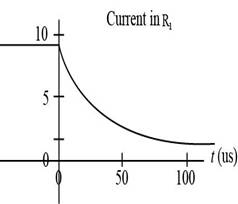
To draw: The graph of currents in
(c)
Answer to Problem 52CP
The graph of currents in

Explanation of Solution
Given info: The battery emf is
The currents in
In

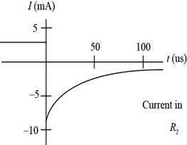
Figure (I)
(d)
The time at which the value of current in
(d)
Answer to Problem 52CP
The time at which the value of current in
Explanation of Solution
Given info: The battery emf is
Formula to calculate the current in the circuit after
Substitute
Take log and solve the equation further,
Conclusion:
Therefore, the time at which the value of current in
Want to see more full solutions like this?
Chapter 31 Solutions
Physics for Scientists and Engineers with Modern Physics


- air is pushed steadily though a forced air pipe at a steady speed of 4.0 m/s. the pipe measures 56 cm by 22 cm. how fast will air move though a narrower portion of the pipe that is also rectangular and measures 32 cm by 22 cmarrow_forwardNo chatgpt pls will upvotearrow_forward13.87 ... Interplanetary Navigation. The most efficient way to send a spacecraft from the earth to another planet is by using a Hohmann transfer orbit (Fig. P13.87). If the orbits of the departure and destination planets are circular, the Hohmann transfer orbit is an elliptical orbit whose perihelion and aphelion are tangent to the orbits of the two planets. The rockets are fired briefly at the depar- ture planet to put the spacecraft into the transfer orbit; the spacecraft then coasts until it reaches the destination planet. The rockets are then fired again to put the spacecraft into the same orbit about the sun as the destination planet. (a) For a flight from earth to Mars, in what direction must the rockets be fired at the earth and at Mars: in the direction of motion, or opposite the direction of motion? What about for a flight from Mars to the earth? (b) How long does a one- way trip from the the earth to Mars take, between the firings of the rockets? (c) To reach Mars from the…arrow_forward
- No chatgpt pls will upvotearrow_forwarda cubic foot of argon at 20 degrees celsius is isentropically compressed from 1 atm to 425 KPa. What is the new temperature and density?arrow_forwardCalculate the variance of the calculated accelerations. The free fall height was 1753 mm. The measured release and catch times were: 222.22 800.00 61.11 641.67 0.00 588.89 11.11 588.89 8.33 588.89 11.11 588.89 5.56 586.11 2.78 583.33 Give in the answer window the calculated repeated experiment variance in m/s2.arrow_forward
 College PhysicsPhysicsISBN:9781305952300Author:Raymond A. Serway, Chris VuillePublisher:Cengage Learning
 University Physics (14th Edition)PhysicsISBN:9780133969290Author:Hugh D. Young, Roger A. FreedmanPublisher:PEARSON
 Introduction To Quantum MechanicsPhysicsISBN:9781107189638Author:Griffiths, David J., Schroeter, Darrell F.Publisher:Cambridge University Press
 Physics for Scientists and EngineersPhysicsISBN:9781337553278Author:Raymond A. Serway, John W. JewettPublisher:Cengage Learning
 Lecture- Tutorials for Introductory AstronomyPhysicsISBN:9780321820464Author:Edward E. Prather, Tim P. Slater, Jeff P. Adams, Gina BrissendenPublisher:Addison-Wesley
 College Physics: A Strategic Approach (4th Editio...PhysicsISBN:9780134609034Author:Randall D. Knight (Professor Emeritus), Brian Jones, Stuart FieldPublisher:PEARSON