
Concept explainers
(a)
Interpretation:
Current follower that will produce a 1.0 V output for 10.0 µA input current should be designed.
Concept introduction:
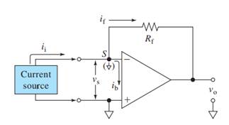
Operational amplifiers can be used to measure or process currents by connecting them in the current follower mode. This mode provides a nearly zero resistance load to the current source and prevents it from being loaded by a measuring device or circuit.

Here,
V+, V- = input voltages
Vs = Input difference voltage
V0 = output voltage
ib = input bias current
if = feedback current
ii = input current
Rf = feedback resistor
Also,
(b)
Interpretation:
Effective input resistance of the current follower designed in part (a) should be calculated.
Concept introduction:

Here,
V+, V- = input voltages
Vs = Input difference voltage
V0 = output voltage
ib = input bias current
if = feedback current
ii = input current
Rf = feedback resistor
Ri = effective input resistance
A = open loop gain
Also,
(c)
Interpretation:
The percent relative error for the circuit designed in part (a) for an input current of 25 µA should be calculated.
Concept introduction:
Here,
V+, V- = input voltages
Vs = Input difference voltage
V0 = output voltage
ib = input bias current
if = feedback current
ii = input current
Rf = feedback resistor
Ri = effective input resistance
A = open loop gain
Here,
Also,
Thus,
Relative error percentage =
Want to see the full answer?
Check out a sample textbook solution
Chapter 3 Solutions
Principles of Instrumental Analysis


- What is the purpose of waiting 1s after a voltage pulse before measuring current in sampled current voltammetry?arrow_forwardElectrochemical detection is commonly used in combination capillary electrophoresis systems. This is a type of hydrodynamic voltammetry called flow injection, where it has been shown that ilim a U1/3, where U is the flow rate of the solution. Flow analysis of a urine sample at a thin-layer amperometric detector, with a flow-rate of 1.25mL/min, yielded a limiting current value of 1.6µA for its unknown uric acid content. A larger current of 2.4µA was observed for a sample containing 1 × 10⁻⁴ M uric acid and flowing at a rate of 0.9mL/min. Calculate the original concentration of uric acid in the samplearrow_forwardThe table shows a series of standard additions of Cu(II)to acidified tap water samples measured by anodic stripping voltammetry at a platinum electrode. The unknown and all standard additions were made up to the same final volume. 1. Plot absorbance as a function of the concentration of Cu (II) standard. Determine the equation of the line and the X intercept. Find the concentration of Cu(II) in the water.arrow_forward
- 7) A 25.0 ml sample containing Cu gave an instrument reading of 23.6 units (corrected for a blank). When exactly 0.500 ml of 0.0287M Cu(NO3)2 Was added to the solution,the signal increased to 37.9 units. Calculate the molar concentration of Cu" in the sample +2,arrow_forward(a) A silicon sample maintained at T = 300 K is uniformly doped with Nd = 1016cm-3 donors. Calculate the resistivity of the sample.arrow_forwardA pH probe has a range of 2 to 10 pH units, and a transmitter converts the pH units into a 4 to 20 mA signal. (a) What are the zero and span for the probe? (b) Determine the gain of the probe/transmitter unit. (c) Determine the transmitter output if the pH of a solution is 5.0. (d) If the transmitter gives a reading of 11 mA, what is the pH of the solution?arrow_forward
- The molar absorptivity for aqueous solutions of phenol at 211 nm is 6.17 × 10³ L cm-1 mol-1. Calculate the permissible range of phenol concentrations if the transmittance is to be less than 85% and greater than 7% when the measurements are made in 1.00-cm cells.arrow_forwardFIGURE 24-8 2µF 4µF HH 3µF HH 6µF 90V A system of capacitors is connected across a 90 V DC voltage source as shown in Fig. 24-8. What is the equivalent capacitance of this system?arrow_forward
 Principles of Instrumental AnalysisChemistryISBN:9781305577213Author:Douglas A. Skoog, F. James Holler, Stanley R. CrouchPublisher:Cengage Learning