Concept explainers
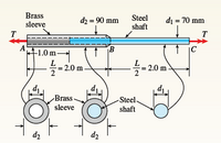
A steel shaft (Gs = 80 GPa) of total length
L = 3.0 m is encased for one-third of its length by a
brass sleeve (Gb =40 GPa) that is securely bonded
to the steel (see figure). The outer diameters of the
shaft and sleeve are d1 = 70 mm and d2 = 90 mm,
respectively.
(a) Determine the allowable torque T1 that may be
applied to the ends of the shaft if the angle of
twist between the ends is limited to 8.0°.
(b) Determine the allowable torque T2 if the shear
stress in the brass is limited to τb = 70 MPa.
(c) Determine the allowable torque T3 if the shear
stress in the steel is limited to τs = 110 MPa.
(d) What is the maximum allowable torque Tmax if
all three of the preceding conditions must be
satisfied?

Trending nowThis is a popular solution!
Step by stepSolved in 3 steps

- A steel stepped shaft ABCD fixed at A is subjected to three torques at points B, C and D, with magnitudes T₁ = 40 kip-in, T₂ = 50 kip-in and Ts= 30 kip-in and directions as shown in Figure 1.1. The segments AB and BC are solid with diameters dx = 3 in and dec = 2 in respectively, while segment CD is hollow with an outer diameter dan 1.5 in and a wall thickness of 0.25 in. The shear modulus of elasticity is equal to G=11.6x10³ ksl. T₁ T₂ 4 = 20 in A B L₂ = 20 in Figure 1.1 a) Draw the torsion moment diagram for the shaft and calculate how long should segment CD be so that the angle of twist between points B and D is equal to zero. T₁ 4₂-25 in b) If Ts is dropped, a fixed support is added at point D (as shown in Figure 1.2) and the length of segment CD is equal to 15 in, find the support reactions at points A and D and the maximum shear stress developed in segment BC. The magnitudes of the torques at points B and Care the same as in part a). B C L₂= 25 in T₂ * Figure 1.2 Hollow C Hollow…arrow_forwardNote: J3 = J2 46 mm G3 = G2 4.93×10° mm (1) 16 kN-m 50 GPa (2) C2 = 34 mm (3) J2 2.10x10° mm* B 900 mm 35 GPa 900 mm A composite torsion member consists of a tubular shell (1) bonded to length AB of a continuous solid T1 kN-m shaft that extends from A to C, which is labeled T2 kN-m (2) and (3). A concentrated torque T is applied to MPa free end C of the shaft in the direction shown. MPa Determine the internal torques and shear stresses PC rad in shell (1) and core (2) (i.e., between A and B). 1st 2nd 3rd Enter Also, determine the rotation angle at end C. attempt II || || I| || || Shaft propertiesarrow_forwardF3.A shaft is composed of two 6-in. diameter sections coupled together (see figure below). Part AB is bronze and part BC is steel. A torque is applied at the free end which causes a maximum shear stress in the bronze shaft of 10,000 psi. Find the angle of twist of the free end. Assume the modulus of rigidity of bronze is 6 (106) psi and that of steel is 12(106) psi. Bronze Dia. = 6 in. A 3' Steel B Match each item to a choice: Angle of twist Tarrow_forward
- Formulate the equation of angle of twist at end C with respect to A in terms of Tarrow_forwardGear shaft ABCDE is subjected to the torques shown in the figure. Find the internal torque in each seg- ment, and then plot the torsional moment diagram. Assume that the spacing between gears is constant, i.e., 10 in. T1 = T2 = 1000 lb-in. 500 lb-in. A B T3 = 800 Ib-in. C Ta = 500 lb-in. d = 1.0 in. D T; = 800 lb-in. Earrow_forwardA shaft ABCD is supported by a clamp at point A and is subjected to point torques at B, C and D, as shown in the figure. The shaft has variable cross-section and is solid in segments AB and CD and hollow in segment BC. The lengths and diameters of each segment are shown in the figure. Assume that the deformation is linear elastic and take the shear modulus of elasticity G = 12.1 × 10° psi. a) Using method of sections, plot the torsion moment diagram. b) Find the angle of twist for the free end (point D) with respect to the fixed support at A, QAD and the angle of twist for point C with respect to the fixed support at A, QCA. Find both angles in degrees. d₁ = 4 in d20 3.5 in, d2=2.5 in d3 = 3.0 in 25 kip-in 20 kip-in 10 kip-in A 20 in B с D ++ 25 in 30 inarrow_forward
 Elements Of ElectromagneticsMechanical EngineeringISBN:9780190698614Author:Sadiku, Matthew N. O.Publisher:Oxford University Press
 Mechanics of Materials (10th Edition)Mechanical EngineeringISBN:9780134319650Author:Russell C. HibbelerPublisher:PEARSON
 Thermodynamics: An Engineering ApproachMechanical EngineeringISBN:9781259822674Author:Yunus A. Cengel Dr., Michael A. BolesPublisher:McGraw-Hill Education
 Control Systems EngineeringMechanical EngineeringISBN:9781118170519Author:Norman S. NisePublisher:WILEY
 Mechanics of Materials (MindTap Course List)Mechanical EngineeringISBN:9781337093347Author:Barry J. Goodno, James M. GerePublisher:Cengage Learning
 Engineering Mechanics: StaticsMechanical EngineeringISBN:9781118807330Author:James L. Meriam, L. G. Kraige, J. N. BoltonPublisher:WILEY


