
(a)
The maximum factored load using Load and Resistance Factor Design (LRFD).
Answer to Problem 3.5.4P
The maximum factored load using LRFD is
Explanation of Solution
Given:
The following figure shows the A36 steel connection with
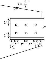
Figure-(1)
Concept Used:
Write the expression for the factored strength in yielding.
Write the expression for the factored strength in rupture.
Here, the factored yielding strength of the material is
Write the expression for block shear.
Write the expression for the upper limit of block shear.
Here, the upper limit is
Write the expression for the design block shear strength.
Here the design block shear strength, the minimum of Equation (III) and (IV), is
The maximum factored load is the minimum of Equation (I), (II), and (V).
Write the expression for the nominal strength in yielding for the tension member.
Here, the yield strength in yielding is
Write the expression for the nominal strength in rupture for the tension member.
Here, the yield strength in rupture is
Write the expression for the effective area.
Here, the area reduction factor is
Write the expression for the area reduction factor.
Here the distance from the centroid of the connected area
Write the expression for the net area of the tension member.
Here, the thickness of the tension member is
Write the expression for the diameter of the holes.
Here the diameter of the bolts is
Calculation:
Calculate the nominal shear strength of the tension member in yielding.
Substitute
Calculate the diameter of the holes.
Substitute
Calculate the net area of the tension member.
Substitute
Calculate the length of the connection.
Calculate the area reduction factor.
Substitute
Calculate the effective area of the member.
Substitute
Calculate the nominal shear strength of the tension member in rupture.
Substitute
Calculate the net area along the shear surface of the tension member.
Calculate the net area along the tension surface of the tension member.
Calculate the gross area along the shear surface in the gusset plate.
Calculate the net area along the shear surface of the gusset plate.
Substitute further.
Calculate the net area along the tension surface of the gusset plate.
Calculate the shear strength for the tension member.
Substitute
Calculate the upper limit.
Substitute
The value of the shear is larger than the upper limit. Hence, it is not feasible.
Adopt the shear strength of the tension member to be
Calculate the shear strength for the gusset plate.
Substitute
Calculate the upper limit
Substitute
The value of the shear is larger than the upper limit. Hence, it is not feasible.
Adopt the shear strength of the gusset plate to be
Compare the shear strength of the tension member and that of the gusset plate.
Thus the block shear strength is
Calculate the design block shear strength of the connection.
Calculate the factored yielding strength.
Substitute
Calculate the factored rupture strength.
Substitute
Calculate the factored strength of block shear.
Substitute
Conclusion:
Thus, the maximum factored load is
(b)
The allowable block shear strength of the connection.
Answer to Problem 3.5.4P
The allowable block shear strength of the connection is
Explanation of Solution
Concept used:
Write the expression for the factored design block shear strength.
Here the safety factor is
Calculation:
Calculate the allowable block shear strength of the connection.
Calculate the allowable yielding strength.
Substitute
Calculate the allowable rupture strength.
Substitute
Calculate the factored strength of block shear.
Substitute
Conclusion:
Thus, the maximum allowable block shear strength of the connection is
Want to see more full solutions like this?
Chapter 3 Solutions
Steel Design (Activate Learning with these NEW titles from Engineering!)

- Pls answer thank you! A flange bolt coupling has 10 steel coupling 1 inch diameter bolts evenly tighten around a 16.34 in. bolt circle. Determine the torque capacity of the connection if the allowable shearing stress in the bolt is 7.3 ksi?arrow_forwardSituation 1A - See Question Below Compute the maximum acceptable tensile SERVICE LOAD that may act on a single tee section that is connected to a gusset plate using welds 12 inches long, as shown in the figure. The service live load is three times the dead load. Use A992 steel. USE LRFD ONLY, no block shear will occur. A. Governing Ultimate Tensile Capacity based on Yielding of gross section Round your answer to 0 decimal places.arrow_forward5. a bolted lap joint shown in the figure below. The bolts are 20m in diameter in 23 mm holes. The plates are 12m thick X350 Allowable stress of Plates: Tenaion in gross area0.60Fy Tension in net area0.50 Fu Shear on Net Area 0.30Fu Yield Strength of plate, Fy 248 Npa Ultinate tensile strength of Plate. Fu400 Mpa x, Find the safe load P based on a- Gross area yielding b. net area rapture c. block shear 2 of 3arrow_forward
- A 1 ⁄2 × 5-inch plate of A588 steel is used as a tension member. It is connected to a gusset plate with four 5 ⁄8-inch-diameter bolts as shown in Figure 1. Assume that the effective net area Ae equals the actual net area An. (a) Calculate the design strength for LRFD? (b) Calculate the allowable strength for ASD?arrow_forwardTwo steel plate tension members have been connected using 0.72 inch diameter bolts arranged in an equally-spaced 9 by 3 rectangular formation. Both plates have a thickness equal to 1/3 in. Take shear fracture stress as 51.2 ksi, clear distance for each edge bolt as 0.12 in, and the clear distance for the other bolts as 1.072 in. a)Sketch the connection showing all the details and measurements with units. b)Find the maximum allowable service dead load and live load assuming live load is half as much as dead load. Consider ASD.arrow_forwardA WT7 x 41 bracket is connected to a W14 x 159 column with 5⁄16inch E70 fillet welds as shown in Figure . What is the maximum factored load Pu that can be supported? What is the maximum service load Pa that can be supported?arrow_forward
- The tension member shown in Figure is an L6 × 3 ½× 5/16. The bolts are ¾ inch ameter. If A36 steel is used, is the member adequate for a total load of 100 kips?arrow_forwardConsider the brace connection in Figure 4.(a) Design number of required M16 bolts to carry the full tensile capacity of the 2PFC100 section considering the gross area only, i.e., the tensile load for designing the bolts is Ag×fy, where Ag is the gross area of the 2PFC100 section and fy is its yield stress. All the bolts are from bolting category 8.3/TB. In this design consider the shear capacity of the bolts only. Figure 1(a) shows the arrangement and spaces between the bolts. Note that the number of bolts shown in this figure does not show the required number of bolts. Assume that all shear plane bolts have threads. It is assumed that the plate has adequate bearing capacity.(b) If instead of bolts in section (a), as Figure 1(b) shows, a fillet weld with an equal leg of size 6 mm is used to carry the tensile load calculate the required weld length, Lw. Each PFC section is welded by two weld lines to the gusset plate. Therefore, there are four lines to transfer the tensile load from the…arrow_forwardGive me right solution according to the question. Note : Don't copy from other websites. I have other website solution. A 620×230 UB 125 tension member of S355 steel is connected through both flanges by 30 mm bolts (in 25 mm diameter bolt holes) in four lines, two in each flange. Check the member for a design tension force of Nt,Ed = 3000 kN.arrow_forward
- an angle bar 100x100x11 mm tension member is connected with 20-mm-dia bolts as shown in the fig. both legs of the angles are connected. use fy=248 MPa and Fu=400 MPa. 1. determine the nominal strength for tensile yielding in the gross section. a. 515.59 kN b. 429.67 kN c. 545.60 kN d. 390.10 kN 2. determine the effective net area of member a. 1573 mm^2 b. 1632 mm^2 c. 1605 mm^2 d. 1815 mm^2 3. determine the nominal strength for tensile rupture in the net area. a. 642 kN b. 730 kN c. 554 kN d. 650 kNarrow_forwardThe unbraced column length of Round HSS 18 x0.5 in A500 Grade C (Fy = 50 ksi) is 30 ft.Determine the design compressive strength of the column using the equations in Chapter E inPart 16 of the AISC Manual. Confirm your answer using the AISC Manual Table 4-5 (pages 4-84,New AISCM) and (pages 4-84, New AISCM). The column has pin supports at both ends ( i.e Kx= Ky = 1.0) columns. Lx = Ly = 30 ftarrow_forwardW 10x45 is connected to two plates with two lines of ¾” bolts as shown below. Determine the tensile strength of the system if Fy = 50 ksi and Fu = 65 ksi.arrow_forward
 Steel Design (Activate Learning with these NEW ti...Civil EngineeringISBN:9781337094740Author:Segui, William T.Publisher:Cengage Learning