Concept explainers
Videos
Define the following examples as path, motion, or function generation cases.
- A telescope aiming (star tracking)
mechanism - A backhoe bucket control mechanism
- A thermostat adjusting mechanism
- A computer printer head moving mechanism
- An XY plotter pen control mechanism
a.
To define:The following examples of telescope aimingcases study given in the problem.
Explanation of Solution
Given information:
The case study of the initial conditions is given that about a telescope aiming or star tracking mechanism.
Calculation:
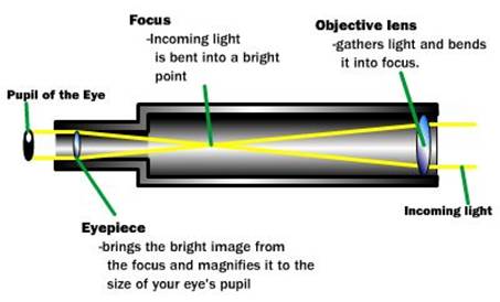
A telescope aiming or star tracking mechanism that shows a path generation. A star goes along the sky with a
The working mechanism in the line diagram is shown below.
b.
To define: The following examples bucket control arrangement case study given in the problem.
Explanation of Solution
Given information:
The case study of the initial conditions is given that about a telescope aiming or star tracking mechanism.
Calculation:
This is motion generation mainly todigging a trench, say; the location and bucket alignment must becontrolled.
The working mechanism in the line diagram is shown below.
c.
To Define:The following example of thermostat adjusting mechanism case study given in the problem.
Explanation of Solution
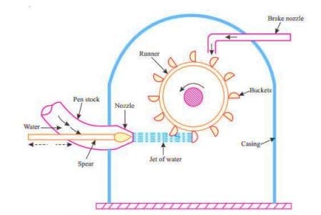
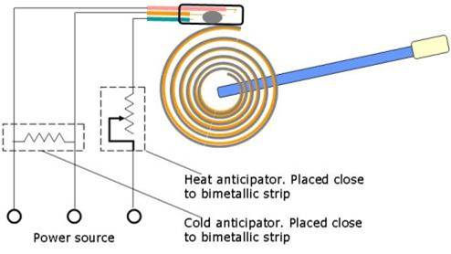
This thermostat adjusting mechanism shows a Function generation.Here the output is a chosen function of input over input range.
The working mechanism in the line diagram is shown below.
d.
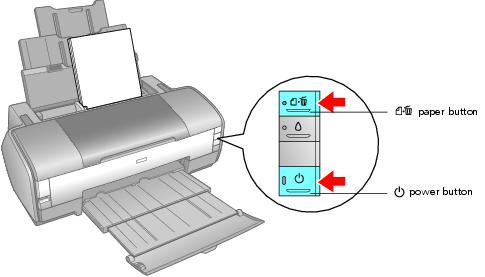
ToDefine:The following example of the computer printing head moving mechanism case study given in the problem.
Explanation of Solution
Here a moving mechanism of a computer printing head shows path generation and head to be point on a path.
The working mechanism in the line diagram is shown below.
e.
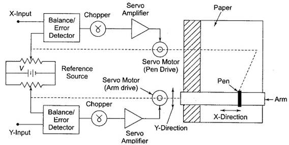
To find:The following examplesof XY plotter pen control mechanism cases study given in the problem.
Explanation of Solution
Here a control mechanism that having an xy plotter pen shows a Path generation and here a pen goes a straight line from point to point.
The working mechanism in the line diagram is shown below.
Want to see more full solutions like this?
Chapter 3 Solutions
Design of Machinery


- How many DOF do the following have in their normal environment ? a. submerged submarineb. An earth-orbiting satellitec. A surface shipd. A motorcyclee. The print head in a 9-pin dot matrix computer printerf. The pen in an XY plotterarrow_forward1) A slider-crank mechanism is a planar mechanism that performs a conversion between the translational motion of a slider and the rotational motion of a crank. It is used in many different engineering applications. A familiar example will be a piston engine. In Figure 1, a basic slider- crank mechanism is shown. В b dạc Figure 1. A basic slider-crank mechanism 0< 0< 2n; b = 20 cm; I= 50 cm 1- Find the angle of Ø and the distance of dAC as a function of 0. 2- If crank AB has a rotational speed of w = 1000 rev/min; find velocity of C (Vc) and velocity and acceleration of link BC (vBC & aBC)arrow_forwardI want you to draw a ladder logic diagram of a garage door to control it by PLC. In my case we have different inputs and outputs and all of them gotta be used in the diagram. I can perfectly interpret the diagram so no need to explain it, I will just require you to draw it. INPUTS : open push button ( OPB ) - close push button ( CPB ) - open limit switch ( OLS ) - close limit switch ( CLS ) - obstacle detection sensor ( ODS ) - safety sensor ( SS ) - emergency stop push button ( ESPB ) - reset button ( RB ) OUTPUTS : motor starts ( MS ) - motor stops ( MSTP ) - motor forward ( MF ) - motor reverse ( MR ) - Error display ( ER ) OPERATİNG MODES : automatic mode ( AM ) - manual mode ( MM ) NECESSARY TIMERS : T1 ( delay door movement after obstacle detection ) - T2 ( delay door movement after reversing ) Here is my excercise for today. Please I am requiring a good logic diagram taking into consideration all what was mentioned before. so to sum up, I want you to write a logic ladder diagram…arrow_forward
- B. Use your own words to describe the method to derive the A-matrix that represents each joint of the SCARA robot above?(Hint: Use your own symbols for joint parameters and links’ lengths).C.Arrange the A-matrices described in part (B) in the correct order necessary to derive the kinematic matrix that defines the motion of the end-effector of the SCARA robot?arrow_forwardDrawing an arc using the polyline command will spawn the same possibilities as employing the arc command alone * O Not relevant at all O True O Falsearrow_forwardSápport Supp Suppórt Support 5 Types of External Connections (Pin, Ball in Socket (3D pin), Fix, Roller/Rocker, Sliding Support, Bearing) Question: Choose the type of External Connections for each image above and explain why?arrow_forward
- 1.In technical terms, what does Robot Manipulator Configuration mean?2.Draw a figure showing a helicoidal joint pointed in the positive x-axis direction of a 3D space?3.How many degrees of freedom does an E-pair have?arrow_forwardDraw the orthographic view of the following component mention top view ,side view,front view . (Use the catia v5R21 software , no hand drawing )arrow_forwardHello, statics please help tabular methodarrow_forward
- Using AutoCAD, draw the following image using object snap modes step by steparrow_forwardWhich type of control system is used in the given block diagram? Write the definition.arrow_forwardA pick and Place machine is being used to transfer a box. The arm is extended (out) by energizing a solenoid valve; when the valve is de-energizes, the arm retracts (in). In the same way, a second valve closes the grip (when energized) or opens the grip (when de-energized). Here's a diagram of this "machine": Grip Air Cylinder Grip open Grip Closed Box Arm Air Cylinder Arm In Arm Out The system is really slow... it actually takes 3-4 seconds for the arm to fully extend. An engineer created the below diagram. Start Pressed Time (seconds) Box Falls - 1 -2 -3 - 4 - 5 -6 –7 -8 – 9 – 10 Extend Arm Close Grip Question (finally!). Which statement is completely true regarding this design? It uses the Master Clock scheme. Given this diagram, the arm will probably start to retract before the grip fully closes. O If the arm takes 4 seconds to retract (return), the box will be dropped "mid-flight" It uses the Domino Scheme. Things can't happen in the wrong sequence. It uses the Master Clock…arrow_forward
 Elements Of ElectromagneticsMechanical EngineeringISBN:9780190698614Author:Sadiku, Matthew N. O.Publisher:Oxford University Press
 Mechanics of Materials (10th Edition)Mechanical EngineeringISBN:9780134319650Author:Russell C. HibbelerPublisher:PEARSON
 Thermodynamics: An Engineering ApproachMechanical EngineeringISBN:9781259822674Author:Yunus A. Cengel Dr., Michael A. BolesPublisher:McGraw-Hill Education
 Control Systems EngineeringMechanical EngineeringISBN:9781118170519Author:Norman S. NisePublisher:WILEY
 Mechanics of Materials (MindTap Course List)Mechanical EngineeringISBN:9781337093347Author:Barry J. Goodno, James M. GerePublisher:Cengage Learning
 Engineering Mechanics: StaticsMechanical EngineeringISBN:9781118807330Author:James L. Meriam, L. G. Kraige, J. N. BoltonPublisher:WILEY