
Engineering Mechanics - Statics, Eighth Edition Si Version
8th Edition
ISBN: 9781119044673
Author: Kraige, Bolton Meriam
Publisher: WILEY
expand_more
expand_more
format_list_bulleted
Concept explainers
Videos
Textbook Question
Chapter 2.5, Problem 77P
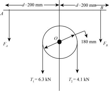
Replace the two cable tensions which act on the pulley at O of the beam trolley by two parallel forces which act at the track-wheel connections A and B.
Expert Solution & Answer
Want to see the full answer?
Check out a sample textbook solution
Students have asked these similar questions
Replace the two cable tensions which act on the
pulley at O of the beam trolley by two parallel
forces which act at pulley connections A and B.
The forces are positive if up, negative if down.
200
mm
160
mm
8.3 KN
200
mm
BO
/B
4.8 KN
A force of magnitude P = 180 N is applied to the stationary machine handle as shown. Write the force and moment reaction at 0 as vectors. Neglect the weight of the handle assembly.
Replace the three forces acting on the plate by a wrench. Specify the magnitude of the force and couple moment for the wrench and the point P(x, y) where the wrench intersects the plate.
Chapter 2 Solutions
Engineering Mechanics - Statics, Eighth Edition Si Version
Ch. 2.3 - The force F has a magnitude of 800 N. Express F as...Ch. 2.3 - The force F has a magnitude of 7 kN and acts at...Ch. 2.3 - The slope of the 6.5-kN force F is specified as...Ch. 2.3 - The force F has a magnitude of 1250 lb and has the...Ch. 2.3 - The control rod AP exerts a force F on the sector...Ch. 2.3 - Two forces are applied to the construction bracket...Ch. 2.3 - Two individuals are attempting to relocate a sofa...Ch. 2.3 - A small probe P is gently forced against the...Ch. 2.3 - The y-component of the force F which a person...Ch. 2.3 - Determine the x-y and n-t components of the 13-kip...
Ch. 2.3 - The two structural members, one of which is in...Ch. 2.3 - The guy cables AB and AC are attached to the top...Ch. 2.3 - If the equal tensions T in the pulley cable are...Ch. 2.3 - Two people exert the forces shown on the potted...Ch. 2.3 - A compressive force F is transmitted via the...Ch. 2.3 - A force F of magnitude 800 lb is applied to point...Ch. 2.3 - The two forces shown act in the x-y plane of the...Ch. 2.3 - Determine the x- and y-components of the tension T...Ch. 2.3 - Refer to the mechanism of the previous problem....Ch. 2.3 - Determine the magnitude Fs of the tensile spring...Ch. 2.3 - Determine the resultant R of the two forces...Ch. 2.3 - A sheet of an experimental composite is subjected...Ch. 2.3 - Determine the scalar components Ra and Rb of the...Ch. 2.3 - Determine the components Fa and Fb of the 4-kN...Ch. 2.3 - If the projection Pa and component Fb of the force...Ch. 2.3 - It is desired to remove the spike from the timber...Ch. 2.3 - At what angle must the 800-lb force be applied in...Ch. 2.3 - Power is to be transferred from the pinion A to...Ch. 2.3 - To insert the small cylindrical part into a...Ch. 2.3 - The unstretched length of the spring is r. When...Ch. 2.4 - Determine the moments of the 5-kN force about...Ch. 2.4 - The force of magnitude F acts along the edge of...Ch. 2.4 - The rectangular plate is made up of 1-ft squares...Ch. 2.4 - Calculate the moment of the 250-N force on the...Ch. 2.4 - An experimental device imparts a force of...Ch. 2.4 - A force F of magnitude 60 N is applied to the...Ch. 2.4 - A man uses a crowbar to lift the corner of a hot...Ch. 2.4 - An overhead view of a door is shown. If the...Ch. 2.4 - The 30-N force P is applied perpendicular to the...Ch. 2.4 - A man exerts a force F on the handle of the...Ch. 2.4 - A 32-lb pull T is applied to a cord, which is...Ch. 2.4 - As a trailer is towed in the forward direction,...Ch. 2.4 - Determine the general expressions for the moments...Ch. 2.4 - The mechanism of Prob. 2/15 is repeated here....Ch. 2.4 - Determine the moments of the tension T about point...Ch. 2.4 - In raising the pole from the position shown, the...Ch. 2.4 - The lower lumbar region A of the spine is the part...Ch. 2.4 - A gate is held in the position shown by cable AB....Ch. 2.4 - In order to raise the flagpole OC, a light frame...Ch. 2.4 - Elements of the lower arm are shown in the figure....Ch. 2.4 - As the result of a wind blowing normal to the...Ch. 2.4 - The masthead fitting supports the two forces...Ch. 2.4 - The small crane is mounted along the side of a...Ch. 2.4 - The 120-N force is applied as shown to one end of...Ch. 2.4 - The bent cantilever beam is acted upon by an 8-kN...Ch. 2.4 - The mechanism shown is used to lower disabled...Ch. 2.4 - The asymmetrical support arrangement is chosen for...Ch. 2.4 - The woman maintains a slow steady motion over the...Ch. 2.5 - The caster unit is subjected to the pair of 80-lb...Ch. 2.5 - For F=65lb, compute the combined moment of the two...Ch. 2.5 - The indicated force—couple system is applied to...Ch. 2.5 - Replace the 3.2-kN force by an equivalent...Ch. 2.5 - As part of a test, the two aircraft engines are...Ch. 2.5 - The cantilevered W530150 beam shown is subjected...Ch. 2.5 - Each propeller of the twin-screw ship develops a...Ch. 2.5 - The upper hinge A of the uniform cabinet door has...Ch. 2.5 - A lug wrench is used to tighten a square-head...Ch. 2.5 - The force F is applied at the end of arm ACD,...Ch. 2.5 - A force F of magnitude 50 N is exerted on the...Ch. 2.5 - An overhead view of a portion of an exercise...Ch. 2.5 - The tie-rod AB exerts the 250-N force on the...Ch. 2.5 - The 20-N force F is applied to the handle of the...Ch. 2.5 - An overhead view of the handlebars on an...Ch. 2.5 - The force F is applied to the leg-extension...Ch. 2.5 - The system consisting of the bar OA, two identical...Ch. 2.5 - The device shown is a part of an automobile seat-...Ch. 2.5 - Replace the two cable tensions which act on the...Ch. 2.5 - The force F acts along line MA, where M is the...Ch. 2.6 - Determine the resultant R of the three tension...Ch. 2.6 - Determine the force magnitude F and direction ...Ch. 2.6 - Replace the three horizontal forces and applied...Ch. 2.6 - Determine the equivalent force-couple system at...Ch. 2.6 - Determine the equivalent force-couple system at O...Ch. 2.6 - Determine the height h above the base B at which...Ch. 2.6 - Where does the resultant of the two forces act?Ch. 2.6 - If the resultant of the loads shown passes through...Ch. 2.6 - If the resultant of the two forces and couple M...Ch. 2.6 - If the resultant of the forces shown passes...Ch. 2.6 - Replace the three forces acting on the bent pipe...Ch. 2.6 - Four people are attempting to move a stage...Ch. 2.6 - Replace the three forces which act on the bent bar...Ch. 2.6 - Uneven terrain conditions cause the left front...Ch. 2.6 - A commercial airliner with four jet engines, each...Ch. 2.6 - Determine the x- and y-axis intercepts of the line...Ch. 2.6 - Replace the three cable tensions acting on the...Ch. 2.6 - Determine the resultant R of the three forces...Ch. 2.6 - For the truss loaded as shown, determine the...Ch. 2.6 - Five forces are applied to the beam trolley as...Ch. 2.6 - As part of a design test, the camshaft-drive...Ch. 2.6 - An exhaust system for a pickup truck is shown in...Ch. 2.7 - Express F as a vector in terms of the unit vectors...Ch. 2.7 - Cable AB exerts a force of magnitude F=6kN on...Ch. 2.7 - Express the 5-kN force F as a vector in terms of...Ch. 2.7 - The force F has a magnitude of 300 1b and acts...Ch. 2.7 - If the tension in the gantry-crane hoisting cable...Ch. 2.7 - The turnbuckle is tightened until the tension in...Ch. 2.7 - If the tension in cable AB is 1750 lb, determine...Ch. 2.7 - The tension in the supporting cable AB is T=425N....Ch. 2.7 - The force F has a magnitude of 2 kN and is...Ch. 2.7 - The tension in the supporting cable AB is 10 kN....Ch. 2.7 - If the tension in cable CD is T=675lb, determine...Ch. 2.7 - If the tension in cable DE is T=575N, determine...Ch. 2.7 - Determine the angle between the 200-lb force and...Ch. 2.7 - Compression member AB is used to hold up the...Ch. 2.7 - Determine a general expression for the scalar...Ch. 2.7 - If the scalar projection of F onto line OA is O,...Ch. 2.7 - The rectangular plate is supported by hinges along...Ch. 2.7 - Express the force F in terms of the unit vectors...Ch. 2.7 - A force F is applied to the surface of the sphere...Ch. 2.7 - Determine the x-, y-, and z-components of force F...Ch. 2.8 - Determine the moment of force F about point O.Ch. 2.8 - Determine the moment of force F about point A.Ch. 2.8 - Determine the moment about O of the force of...Ch. 2.8 - The 4-lb force is applied at point A of the crank...Ch. 2.8 - The steel H-beam is being designed as a column to...Ch. 2.8 - Determine the moment associated with the pair of...Ch. 2.8 - The turnbuckle is tightened until the tension in...Ch. 2.8 - The system of Prob. 2/111 is repeated here, and...Ch. 2.8 - The two forces acting on the handles of the pipe...Ch. 2.8 - The gantry crane of Prob. 2/105 is repeated here,...Ch. 2.8 - Determine the combined moment made by the two...Ch. 2.8 - A helicopter is shown here with certain...Ch. 2.8 - The system of Prob. 2/108 is repeated here, and...Ch. 2.8 - The structure shown is constructed of circular rod...Ch. 2.8 - Two 1.2-lb thrusters on the nonrotating satellite...Ch. 2.8 - If the tension in cable DE is 575 N, determine the...Ch. 2.8 - Determine the moment of each individual force...Ch. 2.8 - The system of Prob. 2/107 is repeated here, and...Ch. 2.8 - A space shuttle orbiter is subjected to thrusts...Ch. 2.8 - The specialty wrench shown in the figure is...Ch. 2.8 - The 75-N force acts perpendicular to the bent...Ch. 2.8 - The body is composed of a slender uniform rod bent...Ch. 2.8 - If F1=450N and the magnitude of the moment of both...Ch. 2.8 - A 1.8-lb vertical force is applied to the knob of...Ch. 2.8 - A basketball player applies a force F=65lb to the...Ch. 2.8 - The special-purpose milling cutter is subjected to...Ch. 2.8 - The force F acts along an element of the right...Ch. 2.8 - The spring of k and unstretched length 1.5R is...Ch. 2.9 - Three forces act at point O. If it is known that...Ch. 2.9 - Three equal forces are exerted on the equilateral...Ch. 2.9 - The thin rectangular plate is subjected to the...Ch. 2.9 - An oil tanker moves away from its docked position...Ch. 2.9 - Determine the x- and y-coordinates of a point...Ch. 2.9 - The two forces and one couple act on the elements...Ch. 2.9 - Represent the resultant of the force system acting...Ch. 2.9 - Determine the force-couple system at O which is...Ch. 2.9 - The portion of a bridge truss is subjected to...Ch. 2.9 - The pulley and gear are subjected to the loads...Ch. 2.9 - The commercial airliner of Prob. 2/93 is redrawn...Ch. 2.9 - Replace the three forces acting on the rectangular...Ch. 2.9 - While cutting a piece of paper, a person exerts...Ch. 2.9 - The floor exerts the four indicated forces on the...Ch. 2.9 - Replace the three forces acting on the structural...Ch. 2.9 - Replace the two forces and one couple acting on...Ch. 2.9 - Replace the two forces acting on the pole by a...Ch. 2.9 - For the system of Prob. 2154, write the moment M...Ch. 2.9 - Replace the two forces which act on the...Ch. 2.9 - For the system of forces in Prob. 2/167, determine...Ch. 2.10 - Using the principles of equilibrium to be...Ch. 2.10 - The three forces act perpendicular to the...Ch. 2.10 - A die is being used to cut threads on a rod. If...Ch. 2.10 - The blades of the portable fan generate a 1.2-lb...Ch. 2.10 - Determine the moment of the force P about point A.Ch. 2.10 - The directions of rotation of the input shaft A...Ch. 2.10 - The control lever is subjected to a clockwise...Ch. 2.10 - For the angular position =60 of the crank OA, the...Ch. 2.10 - Calculate the moment MO of the 250-N force about...Ch. 2.10 - During a drilling operation, the small robotic...Ch. 2.10 - Reduce the given loading system to a force-couple...Ch. 2.10 - The 300500700-mm column is subjected to the...Ch. 2.10 - When the pole OA is in the position shown, the...Ch. 2.10 - The combined action of the three forces on the...Ch. 2.10 - Four forces are exerted on the eyebolt as shown....Ch. 2.10 - The force F is directed from A toward D and D is...Ch. 2.10 - With the 300-lb cylindrical part P in its grip,...Ch. 2.10 - A flagpole with attached light triangular frame is...Ch. 2.10 - Plot the magnitude of the resultant R of the three...Ch. 2.10 - For the previous problem, determine the...Ch. 2.10 - The throttle-control lever OA rotates in the range...Ch. 2.10 - For the rectangular parallelepiped shown, develop...Ch. 2.10 - Consider the rectangular parallelepiped of Prob....Ch. 2.10 - A motor attached to the shaft at O causes the arm...
Additional Engineering Textbook Solutions
Find more solutions based on key concepts
ICA 7-30
A circular window has a 10-inch [in] radius. What is the surface area of one side of the window in uni...
Thinking Like an Engineer: An Active Learning Approach (4th Edition)
The belt passing over the pulley is subjected to forces F1 and F2, each having a magnitude of 40 N. F1 acts in ...
INTERNATIONAL EDITION---Engineering Mechanics: Statics, 14th edition (SI unit)
1.1 What is the difference between an atom and a molecule? A molecule and a crystal?
Manufacturing Engineering & Technology
Solve Ex. 4-4 assuming that the filter is in location A in Fig. 4-9.
Heating Ventilating and Air Conditioning: Analysis and Design
Oil has been flowing from a large tank on a hill to a tanker at the wharf. The compartment in the tanker is nea...
Fox and McDonald's Introduction to Fluid Mechanics
(a) If the cone shown in Fig. 5.34 is made of pine wood with a specific weight of 30lb/ft3, will it be stable i...
Applied Fluid Mechanics (7th Edition)
Knowledge Booster


Learn more about
Need a deep-dive on the concept behind this application? Look no further. Learn more about this topic, mechanical-engineering and related others by exploring similar questions and additional content below.Similar questions
- The 1800lbin. couple is applied to member DEF of the pin-connected frame. Find the internal force systems acting on sections 1 and 2.arrow_forwardA moment of 50lbft about O is required to loosen the nut. Determine the smallest magnitude of the force F and the corresponding angle that will turn the nut.arrow_forwardFind the reaction at A due to the uniform loading and the applied couple. The force reaction is positive if upward, negative if downward. The moment reaction is positive if counterclockwise, negative if clockwise.arrow_forward
- The force F schematizes the tightening actionperformed by the operator. Calculate the moment inB (tightening torque on the nut) of the force F.arrow_forwardA force of magnitude P= 180 N is applied to the stationary machine handle as shown. Write the force and moment reactions at O as vectors. Neglect the weight of the handle assembly.arrow_forwardReplace the three forces acting on the plate by a wrench. Specify the magnitude of the force and couple moment for the wrench and the point P(y,z) where its line of action intersects the plate.arrow_forward
- Problem 3 The throttle-control sector pivots freely at O. If an internal torsional spring exerts a return moment M = 2 N - m on the sector when in the position shown, for design purposes determine the necessary throttle-cable tension T so that the net moment about O is zero. Note that when T is zero, the sector rests against the idle -control adjustment screw at R. 50 mmarrow_forward1. the tow truck's front wheels will belifted off the ground if the moment of the load W about the rear axle exceeds the moment of 3000N weight of the truck. Determine the largest w that may be safely applied 2. the flat plate shown in the figure is acted on by the three couples. replace the three couples with two forces, one acting along the line OParrow_forwardDetermine the magnitude of the pin force at B.arrow_forward
- A force of magnitude P = 181N is applied to the stationary machine handle as shown. Write the force and moment reactions at O as vectors. neglect the weight of the handle assemblyarrow_forwardDetermine internal reaction at the point located between A and C, 0.7 m to the right of A. Disregard the radius of the pulley’s as the radius is not given to us in this problem.arrow_forwardThe two light pulleys are fastened together and form an integral unit. They are prevented from turning about their bearing at O by a cable wound securely around the smaller pulley and fastened to point A. Calculate the magnitude R of the force supported by the bearing O for the applied 25-kN load.arrow_forward
arrow_back_ios
arrow_forward_ios
Recommended textbooks for you
 International Edition---engineering Mechanics: St...Mechanical EngineeringISBN:9781305501607Author:Andrew Pytel And Jaan KiusalaasPublisher:CENGAGE L
International Edition---engineering Mechanics: St...
Mechanical Engineering
ISBN:9781305501607
Author:Andrew Pytel And Jaan Kiusalaas
Publisher:CENGAGE L
Introduction To Engg Mechanics - Newton's Laws of motion - Kinetics - Kinematics; Author: EzEd Channel;https://www.youtube.com/watch?v=ksmsp9OzAsI;License: Standard YouTube License, CC-BY