
Concept explainers
Videos
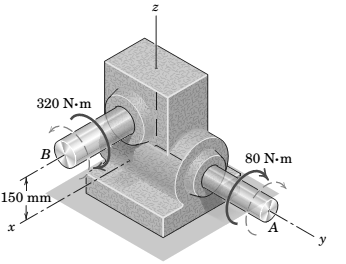
The directions of rotation of the input shaft A and output shaft B of the worm-gear reducer are indicated by the curved dashed arrows. An input torque (couple) of
Want to see the full answer?
Check out a sample textbook solution
Chapter 2 Solutions
Engineering Mechanics - Statics, Eighth Edition Si Version
Additional Engineering Textbook Solutions
DeGarmo's Materials and Processes in Manufacturing
Engineering Mechanics: Statics & Dynamics (14th Edition)
Fox and McDonald's Introduction to Fluid Mechanics
Statics and Mechanics of Materials (5th Edition)
Engineering Mechanics: Dynamics (14th Edition)
Thinking Like an Engineer: An Active Learning Approach (4th Edition)


- 1. Notice the rectangle in the image below. Determine the torque of the forces F, F2, F3, F4, and F, about the shaft through: а. О b. A F 4 m 4 m 3 m F, 3 m F, Please with step by steparrow_forwardThe three forces shown are equivalent to a 50 kN upward force at A and a counterclockwise torque of 170 kN ⋅ m. Determine P and Q.arrow_forwardThe force F = 256 N acts in the xz-plane and is perpendicular to BC. Determine the torque around point A (magnitude). Please respond in newton-meters, not in "pound-feet."arrow_forward
- the three showed forces are equivalent to one ascending force of 50kN in A and has a torque of 170kN*m in couter-clockwise sense. Determine P and Qarrow_forwardThe figure shows a rigid body loaded with a system of forces. If the resultant of this system is a torque of 45 kN.m counterclockwise, determine: 1 The magnitude of P. 2 The magnitude of Q. 3 The magnitude of M. Measured in millimetersarrow_forwardSolve by moving all of the forces to point O.arrow_forward
- The two shafts AB and BC, of equal lengths and diameters d and 2d, are made of the same material. They are joined at B through a shaft coupling, while the ends A and C are built-in. A twisting moment 7 is applied to the coupling. If T and T represent the twisting moments at the ends A and C then find out the relationship between them?arrow_forwardThe shaft-and-pulley assembly ABCD is driven by the 32-N-m torque (couple) supplied by the electric motor at A. The assembly is also subjected to the two belt tensions shown at each of the two pulleys. Determine the force-couple system at A that is equivalent to the torque and the four belt tensions. b Reduce the foce-couple eystem atA into a Wrench and find its tocattont. 12 lb 15 1.0 ft 26 lb -0.75 ft 32 lb ft 3 ft- 8 lb 1.5A 32 lbarrow_forwardTwo shafts of a gearbox are subjected to the torques as given in the figure. Replace these couples with a single equivalent couple, specifying its magnitude and direction of its axis. M2=38 lb-ft M1=18 lb-ftarrow_forward
- Determine the resultant internal torque acting on the cross sections through points B and C. Please help me with this exercise with a complete solution so that I may study it later on. thank you.arrow_forwardA couple acts on the gear teeth as shown in the figure below. Replace it by an equivalent couple having a pair of forces that act through (a) points A and B.arrow_forward4. The gear and attached V-belt pulley are turning counter-dockwise and are subjected to the tooth load of 1600 N and the 800 N and 450 N tensions in the V-belt. Represent the action of these three forces by a resultant force R at O and a couple of magnitude M. Is the unit slowing down or speeding up? 15° 280 mm 150 mm 450 N 30° 800 N 15° 20 1600 Narrow_forward
 Elements Of ElectromagneticsMechanical EngineeringISBN:9780190698614Author:Sadiku, Matthew N. O.Publisher:Oxford University Press
 Mechanics of Materials (10th Edition)Mechanical EngineeringISBN:9780134319650Author:Russell C. HibbelerPublisher:PEARSON
 Thermodynamics: An Engineering ApproachMechanical EngineeringISBN:9781259822674Author:Yunus A. Cengel Dr., Michael A. BolesPublisher:McGraw-Hill Education
 Control Systems EngineeringMechanical EngineeringISBN:9781118170519Author:Norman S. NisePublisher:WILEY
 Mechanics of Materials (MindTap Course List)Mechanical EngineeringISBN:9781337093347Author:Barry J. Goodno, James M. GerePublisher:Cengage Learning
 Engineering Mechanics: StaticsMechanical EngineeringISBN:9781118807330Author:James L. Meriam, L. G. Kraige, J. N. BoltonPublisher:WILEY