Concept explainers
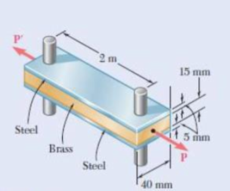
Two steel bars (Es = 200 GPa and αs = 11.7 × 10⁻⁶/°C) are used to reinforce a brass bar (Eb =105 GPa, αb = 20.9 × 10⁻⁶/°C) that is subjected to a load P = 25 kN. When the steel bars were fabricated; the distance between the centers of the holes that were to fit on the pins was made 0.5 mm smaller than the 2 m needed. The steel bars were then placed in an oven to increase their length so that they would just fit on the pins. Following fabrication, the temperature in the steel bars dropped back to room temperature. Determine (a) the increase in temperature that was required to fit the steel bars on the pins, (b) the stress in the brass bar after the load is applied to it.

Fig. P2.55
(a)
The required temperature increment to fit the steel bars on the pins.
Answer to Problem 55P
The required temperature increment to fit the steel bars on the pins is
Explanation of Solution
Given information:
The magnitude of load
The coefficient
The coefficient
The young’s modulus
The young’s modulus
Determine the temperature change require to expand steel bar by this amount.
Here,
Substitute
Thus, the required temperature increment to fit the steel bars on the pins is
(b)
The normal stress in the brass bar after load applied.
Answer to Problem 55P
The normal stress due to steel is
The normal stress due to brass is
Explanation of Solution
Calculation:
After the assembly of the bars, a compressive force is developed in the brass bars and a tensile force is developed in the steel bars.
Determine the area
Here, b is the width of the steel bar , d is the depth of the steel bar, and t is the thickness of the bar.
Substitute
Determine the deformation of steel
Here, F is the compressive force, L is the length of the bar, and
Substitute
Determine the area
Here, b is the width of the brass bar, d is the depth of the brass bar.
Substitute
Determine the deformation of brass
Here,
Substitute
The deformation of bar and steel is equal to the initial amount of misfit.
Here,
Substitute
Find the stresses due to fabrication for steel using the relation:
Substitute
Find the stresses due to fabrication for brass using the relation:
Substitute
The stresses should be added the stress due to the
Consider
Find the force developed in steel bar
Substitute
Find the force developed in brass bar
Substitute
Find the force P as follows:
Here,
Substitute
Substitute
Substitute
Find the normal stress
Substitute
Find the normal stress
Substitute
The stress due to fabrication added.
Find the total stress using the relation:
Here,
Substitute
Thus, the normal stress due to steel is
Find the total stress using the relation:
Substitute
Thus, the normal stress due to brass is
Want to see more full solutions like this?
Chapter 2 Solutions
EBK MECHANICS OF MATERIALS
- A slightly tapered bar AB of solid circular crass section and length L is supported at end B and subjected to a tensile load P at the free end A. The diameters of the bar at ends A and B are dAand dB. respectively. Determine the length of the bar if the elongation of the bar due to the load P = 45 kips is 0.02 in. Assume that E = 10,400 ksi.arrow_forwardA two-story building has steel columns AB in the first floor and BC in the second floor, as shown in the figure. The roof load P:equals 400 KN, and the second-floor load P-, equals 720 kN. Each column has a length L = 3.75 m. The cross-sectional areas of the first- and second-floor columns are 11,000 mm" and 3900 mm", respectively. (a) Assuming that E = 206 GPa. determine the total shortenings aof the two columns due to the combined action of the loads Ptand P,. (b) How much additional load P0can be placed at t he top of t he column (point C) if t he total shortening: SACis not to exceed 4.0 mm?arrow_forwardAxial loads are applied with rigid bearing plates to the solid cylindrical rods shown. The normal stress in aluminum rod (1) must be limited to 19 ksi, the normal stress in brass rod (2) must be limited to 24 ksi, and the normal stress in steel rod (3) must be limited to 12 ksi. Determine the minimum diameter required for each of the three rods. Assume P = 9 kips, Q = 4 kips, R = 18 kips and S = 21 kips. Calculate the internal force (positive if tensile, negative if compresive) in rod (1). Use a FBD cutting through the rod in the section that includes the free end A.Answer: F1 = ? kips.arrow_forward
- Axial loads are applied with rigid bearing plates to the solid cylindrical rods shown. The normal stress in aluminum rod (1) must be limited to 19 ksi, the normal stress in brass rod (2) must be limited to 24 ksi, and the normal stress in steel rod (3) must be limited to 12 ksi. Determine the minimum diameter required for each of the three rods. Assume P = 9 kips, Q = 4 kips, R = 18 kips and S = 21 kips.Calculate the internal force (positive if tensile, negative if compresive) in rod (1). Use a FBD cutting through the rod in the section that includes the free end A.arrow_forwardAxial loads are applied with rigid bearing plates to the solid cylindrical rods shown. The normal stress in aluminum rod (1) must be limited to 19 ksi, the normal stress in brass rod (2) must be limited to 22 ksi, and the normal stress in steel rod (3) must be limited to 14 ksi. Determine the minimum diameter required for each of the three rods. Assume P = 9 kips, Q = 5 kips, R = 20 kips and S = 30 kips. (1) VQ B R (2) C (3) Darrow_forwardAxial loads are applied with rigid bearing plates to the solid cylindrical rods shown. The normal stress in aluminum rod (1) must be limited to 19 ksi, the normal stress in brass rod (2) must be limited to 22 ksi, and the normal stress in steel rod (3) must be limited to 14 ksi. Determine the minimum diameter required for each of the three rods. Assume P = 9 kips, Q = 5 kips, R = 20 kips and S = 30 kips. (1) VQ B (2) (3) D First: Calculate the internal force (positive if tensile, negative if compresive) in rod (1). Use a FBD cutting through the rod in the section that includes the free end A. Answer: F1 = i kips.arrow_forward
- The rigid bar BCE is supported by two links AB and CD as shown in Figure 1. The Link AB is made of aluminum (E = 70 GPa) and the link CD is made of steel (E = 200 GPa). Both links have a Width= 35 mm x thickness= 7 mm rectangular cross-section. Each of the four pins A, B, C and D has a 5 mm diameter. For the 30 kN force at point E,arrow_forward30 kN 90 kN B C 13 30 kN 400 mm 600 mm- The rod shown is made of steel (E= 200 GPa) has a cross sectional area of 1 × 10-³m². The change of length of part AB is most likely equals to: (a) -180 x 10-6 m (b) - 84 x 10-6 m (c) +96 x 10-6 marrow_forwardTHe bracket shown is made of cold drawn steel with Sy=400MPa and Su=480 MPa, and is fastened to a beam made of the same material by five rivets that are made of a steel with Sy=300 MPa and Sut=365 MPa. The thickness of the bracket and the beam are 12 mm and 16 mm respectively.Diameters of the rivets are 20 mm. What safe load F(steady) can be supported by the riveted joint for a factor of safety of 2. Use distortion energy theory of failure.arrow_forward
- The two vertical steel [E = 200 GPa] rods that support rigid bar ABCD are initially free of stress. Rod (1) has an area of A1 = 510 mm? and a length of L1 = 2.6 m. Rod (2) has an area of A2 = 360 mm? and a length of L2 = 1.5 m. Assume dimensions of a = 3.7 m, b = 1.3 m, and c = 1.7 m. After a load of P = 110 kN is applied to the rigid bar at D, determine: (a) the normal stresses in rods (1) and (2) (b) the deflection of the rigid bar at D. y,v (2) L2 a B D x,u Rigid bar b. (1)arrow_forwardIf a solid circular rod having an initial diameter D = 0.03 m and initial length L = 0.8 m, is subjected to a tensile force F = 300 kN, the new diameter will be: Given: The rod is made of steel having Young's modulus E = 200 Gpa and a Poisson's ratio = 0.3. Select one: a. Df= 2.993 mm Ob. Df = 10.92 mm Oc. Df= 3.007 mm Od. Df = 30.02 mm Oe. Df = 29.98 mmarrow_forwardA load F of 500 N is applied in the negative x-direction on rod OA, and a load P of 200 N is applies in the negative z-direction at point B on rod AB. Assume rod AB is fixed to rod OA and rod OA is fixed along the left side to a wall. Point C is along the frontmost edge of rod OA, in the XZ plane. 0.5 m 0.1 marrow_forward
 Mechanics of Materials (MindTap Course List)Mechanical EngineeringISBN:9781337093347Author:Barry J. Goodno, James M. GerePublisher:Cengage Learning
