
Concept explainers
Videos
Bar AB has a cross-sectional area of 1200 mm2 and is made of a steel that is assumed to be elastoplastic with E = 200 GPa and σY = 250 MPa. Knowing that the force F increases from 0 to 520 kN and then decreases to zero, determine (a) the permanent deflection of point C, (b) the residual stress in the bar.
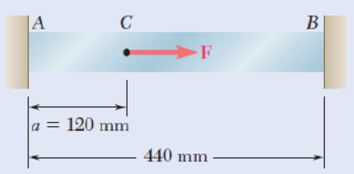
Fig. P2.122
(a)
The permanent deflection of point C.
Answer to Problem 122P
The permanent deflection of point C is
Explanation of Solution
Given information:
The cross sectional area A of section AB is
The modulus of elasticity E is
The yield stress
The force F is
Calculation:
Determine the force at yield portion AC using the relation:
Substitute
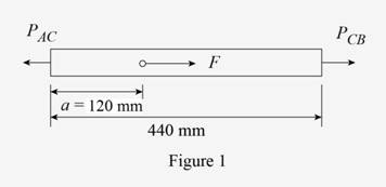
Sketch the bar ACB as shown in Figure 1.
Find the load
Substitute
Find the length
Refer to Figure 1.
Find the deflection at point C using the relation:
Here,
Substitute
Find the stress in rod along CB using the relation:
Substitute
Show the expression of deflection at point C for unloading to find the load
Here,
Substitute
Find the load
Substitute
Calculate the stress at point along AC using the relation:
Substitute
Calculate the stress at point along BC using the relation:
Substitute
Determine the deflection at point C using the relation:
Substitute
Determine the permanent deflection at point C using the relation:
Substitute
Thus, the permanent deflection of point C is
(b)
Find the residual stress in bar AC and CB.
Explanation of Solution
The residual stress in bar AC is
The residual stress in bar CB is
Calculation:
Find the residual stress in bar AC using the relation:
Substitute
Thus, the residual stress in bar AC is
Find the residual stress in bar BC using the relation:
Substitute
Thus, the residual stress in bar CB is
Want to see more full solutions like this?
Chapter 2 Solutions
EBK MECHANICS OF MATERIALS


- Prob.2: [2.24] Each of the links AB and CD is made of aluminum (E = 75 GPa) and has a cross-section area if 125 mm². Knowing that they support the rigid member BC, determine the deflection of point E. |A P = 5 kN 0.36 m E |B -0.44 m 0.20 marrow_forward= P2.39 Two cylindrical rods, AC made of aluminum and CD made of steel, are joined at C and restrained by rigid supports at A and D. For the loading shown and knowing that Ea 10.4 × 10⁶ psi and Es = 29 × 106 psi, determine (a) the reactions at A and D, (b) the deflection of point C. -8 in.- E A 1-¹-in. diameter Fig. P2.39 10 in.-10 in.. B. 18 kips C D 14 kips 15-in. diameterarrow_forwardA pin-connected structure is supported and loaded as shown. Member ABCD is rigid and is horizontal before the load P is applied. Bars (1) and (2) are both made from steel [E = 30,000 ksi] and both have a cross-sectional area of 1.25 in.?. If the normal stress in bar (1) must be limited to 23 ksi, determine the maximum load P that may be applied to the rigid bar. 120 in. 80 in. (2) (1) B C 54 in. 54 in. 24 in. O 40.7 kips O 60.3 kips 32.2 kips 43.1 kipsarrow_forward
- A pin-connected structure is supported and loaded as shown. Member ABCD is rigid and is horizontal before the load P is applied. Bars (1) and (2) are both made from steel [E = 30,000 ksi] and both have a cross-sectional area of 1.25 in.?. If the normal stress in bar (1) must be limited to 31 ksi, determine the maximum load P that may be applied to the rigid bar. 120 in. 80 in. (2) (1) B D 54 in. 54 in. 24 in. Parrow_forward1. Links AB and AC and AD have cross-sectional areas of 80 mm², 30 mm² and 80 mm², respectively. The modulus of elasticity of AB and AD is 70 GPa and that of AC is 210 GPa. Determine the force and stress in each link when a vertical force P of 5 kN is applied at joint A. Assume Hooke's law applies and neglect the weight of the links. B V P=5 KNarrow_forwardPROBLEM 2.62 In a standard tensile test, a steel an aluminum rod of 20-mm diameter is subjected to a tension force of P = 30 kN. Knowing that v 0.35 and E= 70 GPa, determine (a) the elongation of the rod in a 150-mm gage length, (b) the change in diameter of the rod. - 20-mm diameter 150 mm 0.205 mm -0.00955 mmarrow_forward
- PROBLEM 2.62 In a standard tensile test, a steel an aluminum rod of 20-mm diameter is subjected to a tension force of P= 30 kN. Knowing that v=0.35 and E = 70 GPa, determine (a) the elongation of the rod in a 150-mm gage length, (b) the change in diameter of the rod. 20-mm diameter 150 mmarrow_forwardTwo cylindrical rods, one of steel and the other of brass, are joined at C and restrained by rigid supports at A and E. The steel rod has a length of 300 mm while the brass rod has a length of 200 mm. The diameters of the rods are shown in the figure below. A force of 60 kN is applied at point B of the steel segment. For the loading shown and knowing that modulus of elasticity values for steel and brass are respectively Es = 200 GPa and Eb = 105 GPa, determine a.) The reactions at A and E: RA and RE. b.) The deflection of point C from its original location. how to doarrow_forward2.60 At room temperature (20°C) a 0.5-mm gap exists between the ends of the rods shown. At a later time when the temperature has reached 140°C, determine (a) the normal stress in the aluminum rod, (b) the change in length of the aluminum rod. 0.5 mm 300 mm 250 mm B Aluminum Stainless steel A = 2000 mm² E = 75 GPa a = 23 × 16-6/°C Fig. P2.60 A = 800 mm² E = 190 GPa a = 17.3 × 10⁻⁶/°Carrow_forward
- 2.14 The aluminum rod ABC (E 10.1 × 10⁶ psi), which consists of two cylindrical portions AB and BC, is to be replaced with a cylin- drical steel rod DE (E = 29 × 106 psi) of the same overall length. Determine the minimum required diameter d of the steel rod if its vertical deformation is not to exceed the deformation of the aluminum rod under the same load and if the allowable stress in the steel rod is not to exceed 24 ksi. Ĵ 12 in. + 18 in. 28 kips -1.5 in. Fig. P2.14 B -2.25 in. 28 kips D E --arrow_forwardTwo gage marks are placed exactly 250mm apart on a 12mm-diameter aluminum rod with E=73Gpa and an ultimate strength of 140Mpa. Knowing that the distance between the gage marks is 250.28mm after a load is applied, determine (a) the stress in the rod, (b) the factor of safety.arrow_forwardQ1. (A). A 25mm square cross-section bar of length 300mm carries an axial compressive load of 50kN. Determine the stress set up in the bar and its change of length when the load is applied. For the bar material E= 200 GN/m². Q2. A beam AB, 1.2 m long, is simply-supported at its ends A and B and carries two concentrated loads, one of 10 kN at C, the other 15 kN at D. Point C is 0.4 m from A, point D is 1 m from A. Draw the S.F. and B.M. diagrams for the beam. Q3. A solid steel shaft (A) of 50 mm diameter rotates at 250 rev/min. Find the greatest power that can be transmitted for a limiting shearing stress of 60 MN/m2 in the steel.arrow_forward
 Elements Of ElectromagneticsMechanical EngineeringISBN:9780190698614Author:Sadiku, Matthew N. O.Publisher:Oxford University Press
 Mechanics of Materials (10th Edition)Mechanical EngineeringISBN:9780134319650Author:Russell C. HibbelerPublisher:PEARSON
 Thermodynamics: An Engineering ApproachMechanical EngineeringISBN:9781259822674Author:Yunus A. Cengel Dr., Michael A. BolesPublisher:McGraw-Hill Education
 Control Systems EngineeringMechanical EngineeringISBN:9781118170519Author:Norman S. NisePublisher:WILEY
 Mechanics of Materials (MindTap Course List)Mechanical EngineeringISBN:9781337093347Author:Barry J. Goodno, James M. GerePublisher:Cengage Learning
 Engineering Mechanics: StaticsMechanical EngineeringISBN:9781118807330Author:James L. Meriam, L. G. Kraige, J. N. BoltonPublisher:WILEY