
Concept explainers
Videos
The uniform wire ABC, of unstretched length 2l, is attached to the supports shown and a vertical load P is applied at the midpoint B. Denoting by A the cross-sectional area of the wire and by E the modulus of elasticity, show that, for δ << l, the deflection at the midpoint B is

Fig. P2.124
To prove the deflection of uniform wire ABC at midpoint B is
Explanation of Solution
Given information:
The unstretched length is
The vertical load is P.
Calculation:
Sketch the uniform wire ABC as shown in Figure 1.
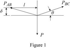
Refer to Figure 1.
The value of
Find the value of vertical load
Substitute for
Find the elongation at point AB using the relation:
Substitute
Sketch the right angle triangle as shown in Figure 2.
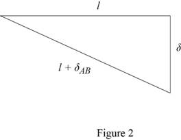
Refer to Figure 2.
Substitute
Hence, the deflection of uniform wire ABC at midpoint B is
Want to see more full solutions like this?
Chapter 2 Solutions
EBK MECHANICS OF MATERIALS


- The rigid bar BDE is supported by two links AB and CD. Link AB is made of aluminum (E = 70 GPa) and has a cross-sectional area of 508 mm2; link CE is made of steel (E = 200 GPa) and has a cross- sectional area of 634 mm2. For the 39 kN force shown, determine %3D the deflection of B (mm) *deflection should have a negative sign if compression and positive if tension. Also, your final answer should have two decimal places 0.4 m 0.3 m D. B 04 m 02 m P.arrow_forwardQ1. (A). A 25mm square cross-section bar of length 300mm carries an axial compressive load of 50kN. Determine the stress set up in the bar and its change of length when the load is applied. For the bar material E= 200 GN/m². Q2. A beam AB, 1.2 m long, is simply-supported at its ends A and B and carries two concentrated loads, one of 10 kN at C, the other 15 kN at D. Point C is 0.4 m from A, point D is 1 m from A. Draw the S.F. and B.M. diagrams for the beam. Q3. A solid steel shaft (A) of 50 mm diameter rotates at 250 rev/min. Find the greatest power that can be transmitted for a limiting shearing stress of 60 MN/m2 in the steel.arrow_forward= P2.39 Two cylindrical rods, AC made of aluminum and CD made of steel, are joined at C and restrained by rigid supports at A and D. For the loading shown and knowing that Ea 10.4 × 10⁶ psi and Es = 29 × 106 psi, determine (a) the reactions at A and D, (b) the deflection of point C. -8 in.- E A 1-¹-in. diameter Fig. P2.39 10 in.-10 in.. B. 18 kips C D 14 kips 15-in. diameterarrow_forward
- Q1. The steel rod AC and brass rod CD are rigidly joined at C. The loads acting are P=60 kN and Q=80 kN. Disregarding the weight of the rods, determine the deflection of (a) point C (b) point D. Given E=200 GPa for steel; E=105 GPa for brass. 2 m B D=40 mm D=25 mm D to 2 m 3 marrow_forwardA 2 m Steel: E = 200 GPa В 50 kN 3 m C 2.5 m Brass: E = 105 GPa 9.18 The 36-mm-diameter steel rod ABC and a brass rod CD of the same diameter are joined at point C to form the 7.5-m rod ABCD. For the loading shown and neglecting the weight of the rod, deter- mine the deflection of (a) point C, (b) point D. V100 kN Fig. P9.18arrow_forwardPortion BC of the rod ABC are made of an aluminum for which E= 70 GPa and portion AB is made of steel for which E = 200 GPa. Given: P = 9 kN, a = 0.6 m, b=0.7 m and the diameter of rod AB is c = 36 mm, (a) Determine the value of Q so that the deflection at A is zero (b) The corresponding deflection of point B 60-mm diameterarrow_forward
- 2. The length of the 2-mm-diameter steel wire CD has been adjusted so that, with no load applied, a gap of 1.5 mm exists between the end Bof the rigid beam ACB and a contact point E. load should be applied to the beam to cause contact between B and E. Using E = 200 GPa, determine where a 225-N 250 mm 225 N 1.5 mm B C A 360 mm 90 mmarrow_forwardProb.3: [2.26] The length of 2 mm diameter steel wire CD has been adjusted so that with no load is applied, a gap of 1.5 mm exists between the end B of the rigid beam ACB and a contact point E. Knowing that E = 200 GPa, determine where a 20 kg block should be placed on the beam in order to cause contact between B and E. 0.25 m CO 20 kg В A E 1.5 mm -0.32 m 0.08 marrow_forwardA pin-connected structure is supported and loaded as shown. Member ABCD is rigid and is horizontal before the load P is applied. Bars (1) and (2) are both made from steel [E = 30,000 ksi] and both have a cross-sectional area of 1.25 in.?. If the normal stress in bar (1) must be limited to 23 ksi, determine the maximum load P that may be applied to the rigid bar. 120 in. 80 in. (2) (1) B C 54 in. 54 in. 24 in. O 40.7 kips O 60.3 kips 32.2 kips 43.1 kipsarrow_forward
- A pin-connected structure is supported and loaded as shown. Member ABCD is rigid and is horizontal before the load P is applied. Bars (1) and (2) are both made from steel [E = 30,000 ksi] and both have a cross-sectional area of 1.25 in.?. If the normal stress in bar (1) must be limited to 31 ksi, determine the maximum load P that may be applied to the rigid bar. 120 in. 80 in. (2) (1) B D 54 in. 54 in. 24 in. Parrow_forwardRigid bar ABC is supported by pin-connected bar (1). Bar (1) is 1.625 in. wide and 1.125 in. thick, and made of aluminum that has an elastic modulus of E= 10,200 ksi. Assume that a = 21 in., b = 36 in., c = 15 in., and d = 26 in. Determine the maximum magnitude of load P that can be applied to the rigid bar without causing member (1) to buckle. A P Answer: P = i a D (1) b M L B lbarrow_forwardThe rigid beam BC is supported by rods (1) and (2). The cross-sectional area of rod (1) is 8 mm². The cross-sectional area of rod (2) is 17 mm². For a uniformly distributed load of w = 2.8 kN/m, determine the length a so that the normal stress is the same in each rod. Assume L = 4.20 m. (1) B Answer: a = i L W E 2arrow_forward
 Elements Of ElectromagneticsMechanical EngineeringISBN:9780190698614Author:Sadiku, Matthew N. O.Publisher:Oxford University Press
 Mechanics of Materials (10th Edition)Mechanical EngineeringISBN:9780134319650Author:Russell C. HibbelerPublisher:PEARSON
 Thermodynamics: An Engineering ApproachMechanical EngineeringISBN:9781259822674Author:Yunus A. Cengel Dr., Michael A. BolesPublisher:McGraw-Hill Education
 Control Systems EngineeringMechanical EngineeringISBN:9781118170519Author:Norman S. NisePublisher:WILEY
 Mechanics of Materials (MindTap Course List)Mechanical EngineeringISBN:9781337093347Author:Barry J. Goodno, James M. GerePublisher:Cengage Learning
 Engineering Mechanics: StaticsMechanical EngineeringISBN:9781118807330Author:James L. Meriam, L. G. Kraige, J. N. BoltonPublisher:WILEY