
Introductory Circuit Analysis (13th Edition)
13th Edition
ISBN: 9780133923605
Author: Robert L. Boylestad
Publisher: PEARSON
expand_more
expand_more
format_list_bulleted
Concept explainers
Videos
Textbook Question
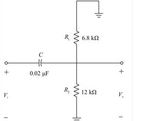
Chapter 22, Problem 39P
- Sketch the response of the magnitude of
- versus frequency for the high-pass filter in Fig. 22.120.
- Using the results of part (a), sketch the response
- for the same frequency range.
- Sketch the idealized Bode plot.
- Sketch the actual response, indicating the dB difference between the idealized and the actual response at
- Determine
- at
- from the plot of part (d), and then determine the corresponding magnitude of
- Sketch the phase response for the same frequency range (the angle by which
Expert Solution & Answer
Want to see the full answer?
Check out a sample textbook solution
Students have asked these similar questions
Consider the unity negative
Bode Diagram
feedback control system
-20
-40
-60
R(s)
K
G(s)
Y(s)
80
-100
Assume that G(s) has the
180
Bode diagram shown.
-270
10-2
101
100
Frequency (rad/s)
10
102
a) Sketch the Nyquist plot of G(s).
b} Let K = 1. Find the steady state error to unit step input.
c) Let K = 10. Find the phase margin and the gain margin
of the system.
%3D
Magnitude (dB)
(Bep) eseyd
Q.5: b. Choose the suitable choice for nine of the following sentences.
1. In order to lune a parallel resonant circuit to a lower frequency. the capacitor must........
> Be decrease.
a. Be increase
d. Remain the same.
e. Be Zero.
2 In series as well as parallel resonance circuit, increase in resistance would cause the bandwidth is......
a. Increase in both circuits. (h. Decrease in series eircuit and increase in parallel circuit.
d. lucrease in series circuit and decrease in parallel circuit.
circuit.
e Decrease in both circuits.
3. In a very low frequency a series resonance circuit behaves as almost purely
a. Resistive.
c. Inductive. d. Inductive and capacitive.
b. Capacitive:
4. Real part of the total impedance at resonance for complicated AC circuit is
a. Positive Value.
b. Zero Value.
5. For admittance locus the maximum obtained power factor is depend on:
a. Maximum current
b. Maximum voltage
c. Minimum power 4. Minimum angle
6. Any non-sinusoidal symmetrical waves are basically…
The figure below plots the frequency response of a multi-pole amplifier. A feedback system employing this amplifier with K = 1 will be:
Bode Diagram
Magnitude (dB)
Phase (deg)
8
0
20
40
-60
-80
-100
-90
10-1
100
10¹
Frequency (rad/s)
Select one:
O a stable because wax Wpx
102
Chapter 22 Solutions
Introductory Circuit Analysis (13th Edition)
Ch. 22 - Determine the frequencies (in kHz) at the points...Ch. 22 - Determine log10 for each value of X. 100,000...Ch. 22 - Given N=log10 , determine for each value of N. 3...Ch. 22 - Determine loge for each value of X. a. 100,000 b....Ch. 22 - Determine log1048=log10(8)(6), and compare to...Ch. 22 - Determine log100.2=log1018/90, and compare to...Ch. 22 - Verify that log100.5 is equal to...Ch. 22 - Prob. 8PCh. 22 - Determine the number of bels that relate power...Ch. 22 - Prob. 10P
Ch. 22 - Prob. 11PCh. 22 - Determine the dBm level for an output power of...Ch. 22 - Find the dBu gain of an amplifier that raises the...Ch. 22 - Prob. 14PCh. 22 - If the sound pressure level is increased from...Ch. 22 - What is the required increase in acoustical power...Ch. 22 - Using semilog paper, plot XL versus frequency for...Ch. 22 - For the meter of Fig. 22.8, find the power...Ch. 22 - For the R-C low-pass filter in Fig. 22.105: Sketch...Ch. 22 - Prob. 20PCh. 22 - Design an R-Clow-pass filter to have a cutoff...Ch. 22 - For the low-pass filter in Fig. 22.107: Fig....Ch. 22 - For the R-C high-pass filter in Fig. 22.108:...Ch. 22 - For the network in Fig. 22.109: Determine...Ch. 22 - Design a high-pass R-C filter to have a cutoff or...Ch. 22 - For the high-pass filter in Fig. 22.110: Determine...Ch. 22 - For the band-pass filter in Fig. 22.111: Sketch...Ch. 22 - Design a band-pass filter such as the one...Ch. 22 - For the band-pass filter in Fig. 22.112...Ch. 22 - Prob. 30PCh. 22 - For the band-stop filter in Fig. 22.114: Determine...Ch. 22 - For the band-pass filter in Fig. 22.115: Determine...Ch. 22 - For the network in Fig. 22.45(a), if...Ch. 22 - Prob. 34PCh. 22 - For the low-pass T filter of Fig. 22.116: In...Ch. 22 - Prob. 36PCh. 22 - For the Butterworth filter of Fig. 22.118: Fig....Ch. 22 - Sketch the idealized Bode plot for Av=Vo/Vi for...Ch. 22 - Sketch the response of the magnitude of...Ch. 22 - Sketch the idealized Bode plot for Av=Vo/Vi for...Ch. 22 - Sketch the response of the magnitude of...Ch. 22 - Prob. 42PCh. 22 - Prob. 43PCh. 22 - For the filter in Fig. 22.125: Sketch the curve of...Ch. 22 - Prob. 45PCh. 22 - Prob. 46PCh. 22 - Prob. 47PCh. 22 - A bipolar transistor amplifier has the following...Ch. 22 - A transistor amplifier has a midband gain of 120,...Ch. 22 - Sketch the Bode plot of the following function:...Ch. 22 - Sketch the Bode plot of the following function:...Ch. 22 - Sketch the Bode plot of the following function:...Ch. 22 - Sketch the Bode plot of the following function:...Ch. 22 - Sketch the Bode plot of the following function...Ch. 22 - Prob. 56PCh. 22 - Using schematics, obtain the magnitude and phase...Ch. 22 - Using schematics, obtain the magnitude and phase...Ch. 22 - Prob. 59PCh. 22 - Prob. 60P
Knowledge Booster


Learn more about
Need a deep-dive on the concept behind this application? Look no further. Learn more about this topic, electrical-engineering and related others by exploring similar questions and additional content below.Similar questions
- Consider a system G(s) in a unity feedback setting, with a bode plot as shown in figure below: Bode Diagram 250 200 150 O 100 50 -50 -100 -150 -135 -180 -270 10 10 102 Frequency (rad's) 101 10° 10' 102 4) The steady state error due to a unit ramp reference is Magnitude (dB) (bap) əseydarrow_forwardQ2 Sketch the asymptotes of the Bode plot magnitude and phase for the controlled transfer function of the system described in the figure, calculate the gain and phase: margins, Take K = 1. d42u42 S+arrow_forward*9. Design a series resonant circuit with an input voltage of 5 V 20° to have the following specifications: a. A peak current of 500 mA at resonance b. A bandwidth of 120 Hz c. A resonant frequency of 8400 Hz Find the value of L and C and the cutoff frequencies.arrow_forward
- An amplifier has a midband voltage gain of 120 operating between f1=10 Hz (lower cut-off) to 100 kHz (upper cut-off). What is the output voltage of the circuit at 3kHz if the input voltage is 20mVpeak-to-peak? 0.85 Vpeak O 1.2 Vrms 1.2 Vpeak O 2.4 Vpeakarrow_forward*9. Design a series resonant circuit with an input voltage of 5V 20° to have the following specifications: a. A peak current of 500 mA at resonance b. A bandwidth of 120 Hz c. A resonant frequency of 8400 Hz Find the value of L and C and the cutoff frequencies. *10. Design a series resonant circuit to have a bandwidth of 400 Hz using a coil with a Q, of 20 and a resistance of 2 2. Find the values of L and C and the cutoff frequen- cies.arrow_forwardEx. 1400. See Fig1400a. MdB= -5 dB, Phdeg=-142.42 deg, w1=12 rad/sec, and w2=1200 rad/sec. The Bode plots of GH are given. Determine (1) closed- loop gain margin (dB), and (2) the closed-loop phase margin (deg) ans:2arrow_forward
- 1. The Bode plots for a plant G(s), used in a unity feedback system are shown in Figure 1. Find the gain margin, phase margin, zero dB frequency, 180° frequency, and the closed-loop bandwidth. 20 log M Phase (degrees) 40 20 -20 -40 -60 -80 -100 0.1 -50 -100 -150 -200 -250 -300 0.1 Frequency (rad/s) Figure 1. Frequency response for G(s) 10 10 100 100arrow_forwardSolve all parts: 1) what is type of filter ? How does it work ? 2) Transfer function of filter ( V0/Vi) 3) What are equations of cut of frequencies ( fH ,fL) and centre frequency (f0). 4)Assume we have resistor 6800 ohm and 470 ohm , capacitor 0.47 μF and 1 μF. What are the R1,R2,C1,C2 ? Calculate (fH ,fL , f0) and bandwidth of filter.arrow_forwardFor the low-pass active filter shown below, the transfer function is expressed as: V. Zc V: ZR + Zc where: 106 Zc ja rad w = angular frequency in ZR = 2000 ZR V. Vị - Zc Vo can be written as: Vi 4-A) Show that the Vo 500 Vị 500 + jw Vo What should be the value of w so that the magnitude of Vi is ? 4-B) 4-C) With w = 1250 rad/s, and V; = 9ej1.8 – j10 volts, evaluate the magnitude and phase of V. Vo (Hint: evaluate 2 in polar form, and Vị in polar form, then V, = 2x V; ) Vị 4-D) When 4 modules of this filter are cascaded, the total transfer function will be (2) . Use de Moivre's Theorem to find the expression of the total transfer function in polar form. Then, find determine the value of w so that the magnitude of the total transfer function is ? V10arrow_forward
- Determine the gain, Vout/ Vin, for the given circuit. What is the resonant frequency of the circuit, in Hertz? + Vout Vinarrow_forward1. A tuned circuit has a resonant frequency of 18 MHz and a bandwidth of 120 kHz. What are the upper and lower cutoff frequencies?2. What value of Q is needed to achieve a bandwidth of 4 kHz at 3.6 MHz?3. A filter has a 6-dB bandwidth of 3500 Hz and a 60-dB bandwidth of 8400 Hz. What is the shape factor?arrow_forwardThe values of d and X in the given bode curve are as follows:d=100 kHz, X=5.4The Rf (feedback) resistance of the operational amplifier to be used for the gain of the filter is 8 K ohms.In the first order active operational amplifier filter that will result in this curve, the values of the other resistors will be equal.In this case, what should be the value of the capacitor to be used in the high pass filter?arrow_forward
arrow_back_ios
SEE MORE QUESTIONS
arrow_forward_ios
Recommended textbooks for you
 Introductory Circuit Analysis (13th Edition)Electrical EngineeringISBN:9780133923605Author:Robert L. BoylestadPublisher:PEARSON
 Delmar's Standard Textbook Of ElectricityElectrical EngineeringISBN:9781337900348Author:Stephen L. HermanPublisher:Cengage Learning
 Programmable Logic ControllersElectrical EngineeringISBN:9780073373843Author:Frank D. PetruzellaPublisher:McGraw-Hill Education
 Fundamentals of Electric CircuitsElectrical EngineeringISBN:9780078028229Author:Charles K Alexander, Matthew SadikuPublisher:McGraw-Hill Education
 Electric Circuits. (11th Edition)Electrical EngineeringISBN:9780134746968Author:James W. Nilsson, Susan RiedelPublisher:PEARSON
 Engineering ElectromagneticsElectrical EngineeringISBN:9780078028151Author:Hayt, William H. (william Hart), Jr, BUCK, John A.Publisher:Mcgraw-hill Education,
Introductory Circuit Analysis (13th Edition)
Electrical Engineering
ISBN:9780133923605
Author:Robert L. Boylestad
Publisher:PEARSON
Delmar's Standard Textbook Of Electricity
Electrical Engineering
ISBN:9781337900348
Author:Stephen L. Herman
Publisher:Cengage Learning
Programmable Logic Controllers
Electrical Engineering
ISBN:9780073373843
Author:Frank D. Petruzella
Publisher:McGraw-Hill Education
Fundamentals of Electric Circuits
Electrical Engineering
ISBN:9780078028229
Author:Charles K Alexander, Matthew Sadiku
Publisher:McGraw-Hill Education
Electric Circuits. (11th Edition)
Electrical Engineering
ISBN:9780134746968
Author:James W. Nilsson, Susan Riedel
Publisher:PEARSON
Engineering Electromagnetics
Electrical Engineering
ISBN:9780078028151
Author:Hayt, William H. (william Hart), Jr, BUCK, John A.
Publisher:Mcgraw-hill Education,
What is Filter & Classification of Filters | Four Types of Filters | Electronic Devices & Circuits; Author: SimplyInfo;https://www.youtube.com/watch?v=9x1Sjz-VPSg;License: Standard Youtube License