
Introductory Circuit Analysis (13th Edition)
13th Edition
ISBN: 9780133923605
Author: Robert L. Boylestad
Publisher: PEARSON
expand_more
expand_more
format_list_bulleted
Concept explainers
Videos
Textbook Question
Chapter 22, Problem 37P
For the Butterworth filter of Fig. 22.118:
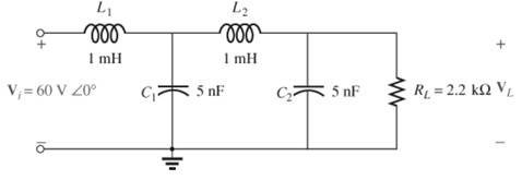
Fig. 22.118
- In words without any calculations, describe the network response to a wide range of frequencies.
- Plot the response of the filter to a range of frequencies extending from 0 Hz to 1 MHz.
Expert Solution & Answer
Want to see the full answer?
Check out a sample textbook solution
Students have asked these similar questions
22.21 Design an RC Low Pass Filter (LPF) to have a cut-off frequency of 500 Hz using a resistor (R) of 1.2 k2.
Sketch the resulting magnitude and phase plot for a frequency range of 0.1fo to 10fo.
Discuss and explain the operation of filter
Can we obtain a plot of XL against frequency f experimentally?
Chapter 22 Solutions
Introductory Circuit Analysis (13th Edition)
Ch. 22 - Determine the frequencies (in kHz) at the points...Ch. 22 - Determine log10 for each value of X. 100,000...Ch. 22 - Given N=log10 , determine for each value of N. 3...Ch. 22 - Determine loge for each value of X. a. 100,000 b....Ch. 22 - Determine log1048=log10(8)(6), and compare to...Ch. 22 - Determine log100.2=log1018/90, and compare to...Ch. 22 - Verify that log100.5 is equal to...Ch. 22 - Prob. 8PCh. 22 - Determine the number of bels that relate power...Ch. 22 - Prob. 10P
Ch. 22 - Prob. 11PCh. 22 - Determine the dBm level for an output power of...Ch. 22 - Find the dBu gain of an amplifier that raises the...Ch. 22 - Prob. 14PCh. 22 - If the sound pressure level is increased from...Ch. 22 - What is the required increase in acoustical power...Ch. 22 - Using semilog paper, plot XL versus frequency for...Ch. 22 - For the meter of Fig. 22.8, find the power...Ch. 22 - For the R-C low-pass filter in Fig. 22.105: Sketch...Ch. 22 - Prob. 20PCh. 22 - Design an R-Clow-pass filter to have a cutoff...Ch. 22 - For the low-pass filter in Fig. 22.107: Fig....Ch. 22 - For the R-C high-pass filter in Fig. 22.108:...Ch. 22 - For the network in Fig. 22.109: Determine...Ch. 22 - Design a high-pass R-C filter to have a cutoff or...Ch. 22 - For the high-pass filter in Fig. 22.110: Determine...Ch. 22 - For the band-pass filter in Fig. 22.111: Sketch...Ch. 22 - Design a band-pass filter such as the one...Ch. 22 - For the band-pass filter in Fig. 22.112...Ch. 22 - Prob. 30PCh. 22 - For the band-stop filter in Fig. 22.114: Determine...Ch. 22 - For the band-pass filter in Fig. 22.115: Determine...Ch. 22 - For the network in Fig. 22.45(a), if...Ch. 22 - Prob. 34PCh. 22 - For the low-pass T filter of Fig. 22.116: In...Ch. 22 - Prob. 36PCh. 22 - For the Butterworth filter of Fig. 22.118: Fig....Ch. 22 - Sketch the idealized Bode plot for Av=Vo/Vi for...Ch. 22 - Sketch the response of the magnitude of...Ch. 22 - Sketch the idealized Bode plot for Av=Vo/Vi for...Ch. 22 - Sketch the response of the magnitude of...Ch. 22 - Prob. 42PCh. 22 - Prob. 43PCh. 22 - For the filter in Fig. 22.125: Sketch the curve of...Ch. 22 - Prob. 45PCh. 22 - Prob. 46PCh. 22 - Prob. 47PCh. 22 - A bipolar transistor amplifier has the following...Ch. 22 - A transistor amplifier has a midband gain of 120,...Ch. 22 - Sketch the Bode plot of the following function:...Ch. 22 - Sketch the Bode plot of the following function:...Ch. 22 - Sketch the Bode plot of the following function:...Ch. 22 - Sketch the Bode plot of the following function:...Ch. 22 - Sketch the Bode plot of the following function...Ch. 22 - Prob. 56PCh. 22 - Using schematics, obtain the magnitude and phase...Ch. 22 - Using schematics, obtain the magnitude and phase...Ch. 22 - Prob. 59PCh. 22 - Prob. 60P
Knowledge Booster


Learn more about
Need a deep-dive on the concept behind this application? Look no further. Learn more about this topic, electrical-engineering and related others by exploring similar questions and additional content below.Similar questions
- Q.) What type of filter is the given circuit?arrow_forwardPlease design the filter according to the questionarrow_forwardUsing a d.c. voltmeter and a.c. voltmeter to measure the output filter of a power supply, the obtain readings are 25 Vd.c. and 1.5 Vrms. Calculate the ripple of the filter output voltage.arrow_forward
- The signal-to-noise ratio is 30dB at the input to an amplifier and 27.3dB at the output. What is the noise temperature in kelvin?arrow_forwardPlease find below the question 1. please let me know which selection is right and give me detailed info. 1)A waveform consisting of frequency components 200kHz, 210kHz, 220kHz, 230kHz and 240kHz is passed through a bandpass filter. The most likely components to be found at the output would be:a) 200kHz, 210kHz, 230kHz and 240kHzb)10kHz and 40kHzc) 20kHz and 30kHzd) 220kHz and 230kHzarrow_forwardWhich of the following diode is used in high frequency switching operations? O a. General purpose diode O b. Schottky diode PN junction diode O d. Şilicon junction diode Choose the % derating factor of the string which is having 9 number of SCR connected in series to withstand a DC voltage of 1733 V and steady state voltage rating of 896 V. O a. 78.51 O b. 10.75 Oc. 21.49 O d. 5.74 o searcharrow_forward
- 2. What is a filter? Why it is necessary? Explain with circuit diagram?arrow_forwardApproximately, determine the Vpp and frequency of the given signal: Reading settings: 20V/DIV and 5ms/DIV Explain your approximationarrow_forwarda. What are the parts and functions of a regulated power supply b. How does a C - filter work? around 5 sentences plsarrow_forward
- 4kHz audio signal with a 40000kHz carrier in a nonlinear circuitFind all the frequency components obtained at the output when mixed?arrow_forwardQ.2:- a) Explain what a band-pass filter is, and how it differs from either a low-pass or a high-pass filter circuit. Also, explain what a hand-stop filter is, and draw Bode plots representative of both band-pass and band-stop filter types. b) What is the purpose (ll) of the parity bit during data transmission?arrow_forwardDiscrete Signals and Discrete Time systemsx[n1] = (values) 9 random integer values from -10 to 5x[n2] = (values) 9 random integer values from -5 to 5 a. Plot the graph setting the middle integer value at n = 0 showing the all samples.b. Plot the graph x[-n] showing all the samples.c. Plot the graph x[n-3] showing all the samples.d. Plot the graph x[n+2] showing all the samples.e. Plot the graph x[2n] showing all the samples.f. Plot the graph x[n/3] showing all the samples.g. Evaluate the convolution of x[n1] and x[n2].arrow_forward
arrow_back_ios
SEE MORE QUESTIONS
arrow_forward_ios
Recommended textbooks for you
 Introductory Circuit Analysis (13th Edition)Electrical EngineeringISBN:9780133923605Author:Robert L. BoylestadPublisher:PEARSON
 Delmar's Standard Textbook Of ElectricityElectrical EngineeringISBN:9781337900348Author:Stephen L. HermanPublisher:Cengage Learning
 Programmable Logic ControllersElectrical EngineeringISBN:9780073373843Author:Frank D. PetruzellaPublisher:McGraw-Hill Education
 Fundamentals of Electric CircuitsElectrical EngineeringISBN:9780078028229Author:Charles K Alexander, Matthew SadikuPublisher:McGraw-Hill Education
 Electric Circuits. (11th Edition)Electrical EngineeringISBN:9780134746968Author:James W. Nilsson, Susan RiedelPublisher:PEARSON
 Engineering ElectromagneticsElectrical EngineeringISBN:9780078028151Author:Hayt, William H. (william Hart), Jr, BUCK, John A.Publisher:Mcgraw-hill Education,
Introductory Circuit Analysis (13th Edition)
Electrical Engineering
ISBN:9780133923605
Author:Robert L. Boylestad
Publisher:PEARSON
Delmar's Standard Textbook Of Electricity
Electrical Engineering
ISBN:9781337900348
Author:Stephen L. Herman
Publisher:Cengage Learning
Programmable Logic Controllers
Electrical Engineering
ISBN:9780073373843
Author:Frank D. Petruzella
Publisher:McGraw-Hill Education
Fundamentals of Electric Circuits
Electrical Engineering
ISBN:9780078028229
Author:Charles K Alexander, Matthew Sadiku
Publisher:McGraw-Hill Education
Electric Circuits. (11th Edition)
Electrical Engineering
ISBN:9780134746968
Author:James W. Nilsson, Susan Riedel
Publisher:PEARSON
Engineering Electromagnetics
Electrical Engineering
ISBN:9780078028151
Author:Hayt, William H. (william Hart), Jr, BUCK, John A.
Publisher:Mcgraw-hill Education,
What is Filter & Classification of Filters | Four Types of Filters | Electronic Devices & Circuits; Author: SimplyInfo;https://www.youtube.com/watch?v=9x1Sjz-VPSg;License: Standard Youtube License